In addition to connecting to a Workspace through Altium Designer – interfacing to it through the Explorer panel and Components panel (for direct interaction with the components therein) – you also connect to it through a dedicated browser interface, with access to management interfaces for the various services available as part of the Workspace. In fact, with some of these services, your only interaction with them is through this browser interface.
For all levels of Altium Solutions discussed in this documentation, the general terms Altium Designer and Altium Workspace are used.
Accessing the Interface
The browser-based interface to a Workspace is presented as a constituent part within the overall Altium 365 Platform Interface. Access to this interface can be performed in a number of ways. Refer to the section Signing in to the Interface, on the Altium 365 Platform Interface page for more details.
What's Provided?
Within the Altium 365 Platform Interface, the area for the active Workspace provides a number of key technologies and services and can be coarsely divided into two groupings, as shown in the following image and listed thereafter.
In the above images:
-
Interface elements that can be accessed by any Workspace user. To access a page, click on its name within the left-hand navigation tree.
-
Interface elements that can only be accessed by a Workspace Administrator. A user is granted administrative powers by membership to the Administrators group. To access a page, choose the required entry within the Admin section of the left-hand navigation tree.
The User drop-down menu at the far right of the upper banner area provides access to your own Personal Space (click My Personal Space), from where you can independently upload snapshots of designs in various supported formats, and manufacturing data (Gerber), which you can then share persistently with others as you wish. 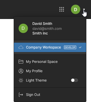 If you have access to multiple Workspaces, this menu also allows you to switch between them.
General Access Interface Elements
The following sections summarize the elements of the Workspace browser interface that can be accessed by all users of the Workspace – both administrators and members.
Help and Resources
As a new Workspace member you are invited to nominate a working role that best fits your needs, which once selected, will open the current Altium Workspace Getting Started guide within the browser interface.
Home
This page is the starting point for using the design and management tools available to the Workspace. Each tile provides direct access to application portals within the Workspace environment, or in the case of Altium Designer and MCAD CoDesigner, access to their installation – see Installing Altium Designer Develop and Installing Altium Designer Agile. Also provided is a standard ‘9-dots’ menu ( ) at the right of the upper banner that provides direct access to the available Workspace portals, which open in a new browser tab.
As you access each portal the Workspace user interface and features change accordingly:
Projects
Related pages: Workspace Projects, Management of a Specific Project, Altium Designer Environment
This page provides the interface to the Projects service and is effectively the Workspace Design Portal. It provides a central, CAD-centric location to create, upload and manage projects, and also share them (by setting access permissions) for team collaboration as required. The page lists all Workspace design projects, which target the development stage of the project lifecycle, simplifying the creation and ongoing workflow for version-controlled projects.
The advantage of Workspace Projects is that they are version controlled by default and can be collaboratively worked upon without having to worry about shared drives, servers, agreements etc. Version control is handled courtesy of the Workspace's built-in GIT version control service. All projects are stored in a single Design Repository within a Workspace, named Versioned Storage (a Git repository).
If your project is under external version control, you can migrate it to be a fully managed project in the Workspace that hosts the design files in the server's own Git repository (effectively switching to the Workspace's native VCS). For detailed information on how to do this, see Moving from External VCS to Workspace Native VCS.
You can also keep your project unmanaged (a regular, or VCS-based project), but make a synchronized
copy of it available online – sending it to your Workspace. Referred to as
Simple Sync, this enables you to take advantage of the collaborative benefits offered through Altium 365.
 Centralized management of your design projects – all part of your Workspace.
Design files and projects from a range of software, including Altium Designer, can be uploaded directly from your PC into the Workspace with the Upload options available from the  button menu. In the browser window that follows, specify a folder containing the project files to upload.
A project created/uploaded through this interface, or through Altium Designer, will initially be available to the designer who created it (the Owner) and Workspace Administrators. In addition to these permissions, the project will inherit the Users/Groups who have access to the project’s parent folder or it will adopt a specific set of permissions defined by a Workspace Administrator.
In the latter case, the Default permissions for new projects option (if available in your Workspace) is enabled in the Admin - Settings – Projects view. The settings here will define which Users/Groups have access to a newly created project, rather than those inherited from the project’s parent folder.
See Managing Project Creation Permissions for more information.
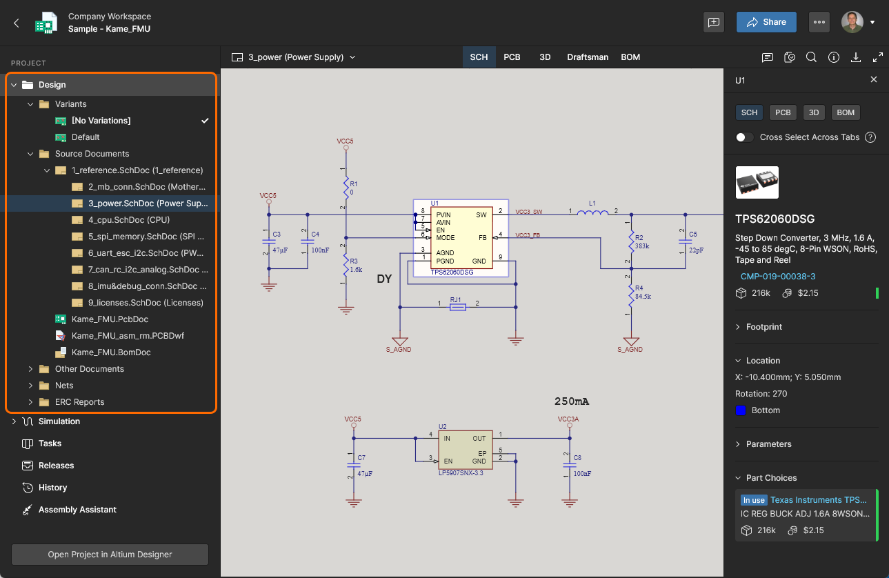
You also can access a detailed, CAD-centric view of the project, opened by clicking on the project’s name, selecting the Open option from the  control above the listing of projects, or by double-click directly on the required project entry in the list view. The detailed management page for that project opens in a new browser tab incorporating the CAD-centric interface, which offers options including Design, Simulation, Releases, History, and Assembly views:
-
Design – display and navigate source project design documents, view design object properties and place review comments. This view uses the Web Viewer interface to present your design across five distinct data sub-views, to show the source schematic(s), board in 2D, board in 3D, Draftsman document and Bill of Materials, respectively. This view is for the latest version of the source project data, rather than a specified release from that project, and so could be considered to be a work-in-progress (WIP) view. You can review both the base design and any of its defined variants.
You'll be able to search, select, cross-probe, and inspect components and nets throughout the design and across the various sub-views as applicable. And when viewing the board in 2D, you can even take measurements.
-
Simulation – allows you to upload circuit simulation results files that will be associated with the current project or project Release. The files are effectively attached to the project, which allows members of the Workspace to inspect and/or download simulation results documents that relate to the currently open project. See Management of a Specific Project – Simulation for more information.

-
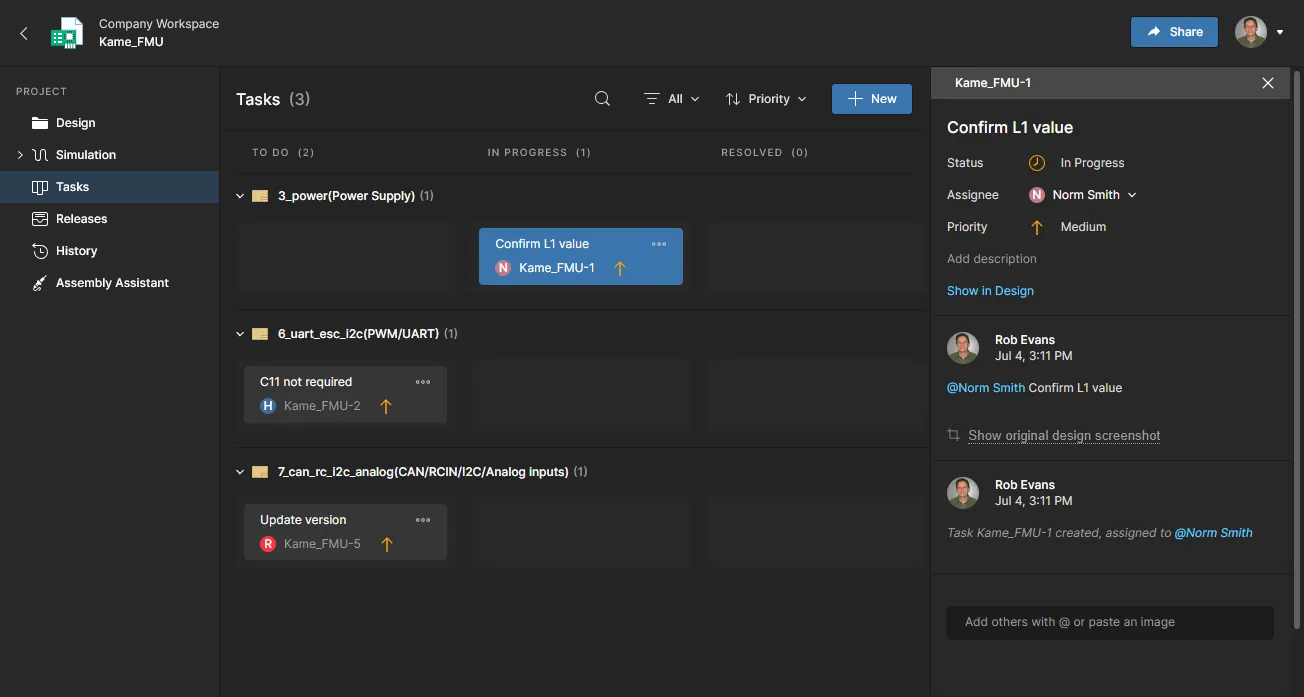
Tasks – view, access and manage all Tasks (job activity requests) that apply to the open Workspace project. These include a row of general Tasks that are associated with the project itself (created within the Tasks view), and collapsible rows of tasks that apply to specific project documents (created in the Design view by assigning a Comment to a Workspace member). The state of Tasks are progressed by moving them through the ToDo, InProgress and Resolved rows. See the Working with Tasks page for more information.
The type of Tasks available in the dashboard is determined by the level of purchased Altium product access, and can include Tasks for Design Reviews, Jira, Requirements and those generated by Process Workflows.
-
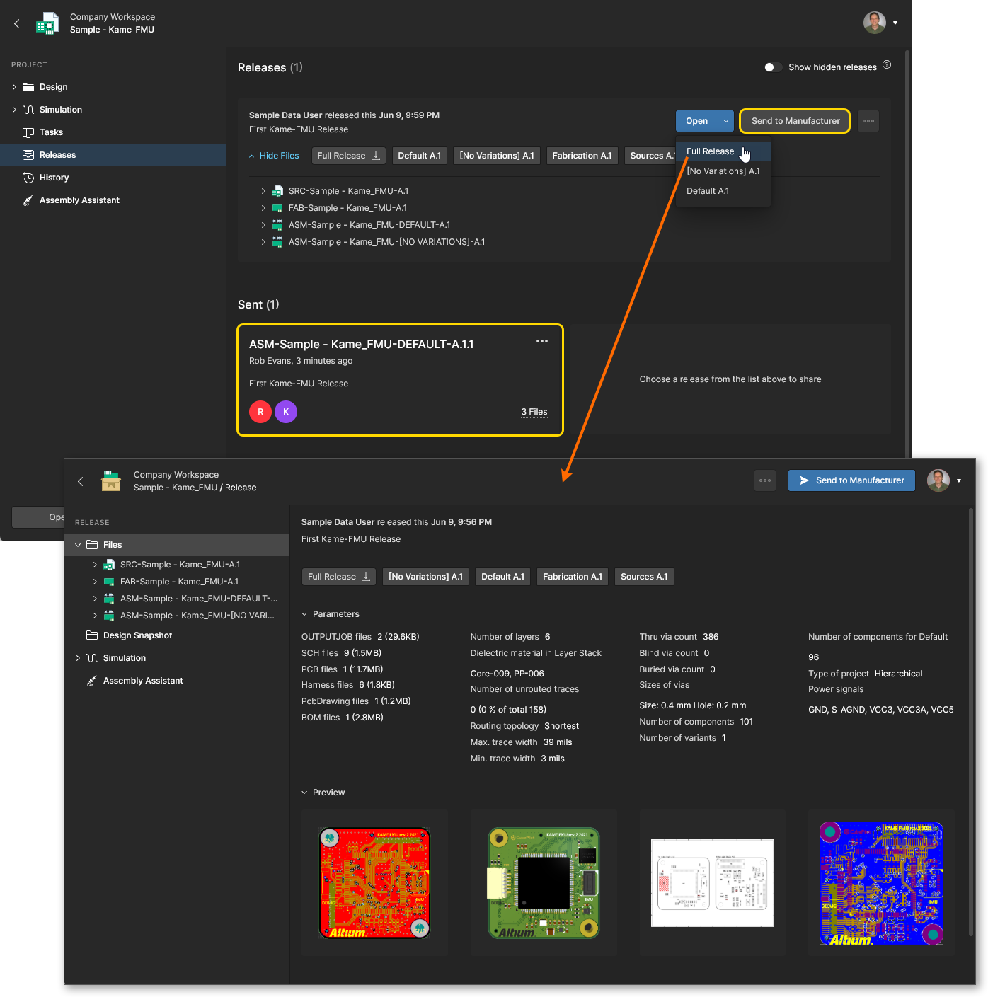
Releases – view the releases for the project. Access is provided for opening the full release data or a specific assembly package, which will be presented on a separate tab through a Manufacturing Portal. From this portal you can view and navigate the released file data, inspect the BOM, and view and comment on the snapshot of the design itself; the source for that released data. From either the Releases view or through the Manufacturing Portal for a specific release, you'll have access to controls for downloading manufacturing data at various levels of granularity (from full data set(s) to individual generated output files). A chosen release can also be sent – as a Manufacturing Package – directly to your manufacturer. You also have the ability to compare Gerber data between releases or against a locally-generated file set, and compare Schematic data, PCB data or BOM data between releases.
The Altium Platform provides a dedicated Manufacturing Package Viewer – an element of the platform's Global Sharing support – which allows others to view a manufacturing package from any browser – anywhere in the world – but outside of your Workspace, so that your designs themselves and other valuable IP are not exposed. For more information, see Global Sharing and Manufacturing Package Viewer.
-
Activities – view the active or closed Project Activity process workflows associated with the current project, or invoke a new activity workflow from the  button. The available Project Activity workflows, such as Ad Hoc, Milestone and Handoff reviews, will include those processes enabled on the Admin – Processes page.
The listed processes provide an overview of the state of each process, including its instigator and who it is assigned to, when it was invoked, and the current stage of its workflow. Select a Process entry to view additional detail that includes its notated workflow diagram, a summary of its associated process data, and the sequential history of its workflow events. Tasks are automatically created for each process step and can be viewed and progressed through the Tasks page.
-
Design Reviews – view and access a tiled listing of the project’s Design Review processes with an In Progress status (by Default), or by clearing the status Filter, also those that have been Rejected or Cancelled. Created and managed through a dedicated user interface, Design Reviews are a configurable peer-review process that includes design content snapshots, definable Checklists, Reviewer user assignments, and design change comparisons. 
Active reviews are accessed and approved/rejected by the assigned Reviewer through an opened Design Review instance or via Tasks page, and then ultimately moved to completion by the review Initiator (creator). See detailed information on the Design Reviews page.
-
History – browse a progressive timeline of major events relating to the project, including its creation, commits, releases, clones and MCAD exchanges. Each time a supported event happens in association with the project, that event is added to the timeline as a dedicated tile with various actions supported where applicable. You also have the ability to compare Schematic, PCB and BOM data between releases and commits, and compare Gerber data between releases or against a locally generated file set. See Project History and Design Data Comparisons for more information.

Library
The Workspace Library entry exposes sub entries that include pages related to component part items and their management. These provide access to Workspace components, an assessment of their health (suitability and any issues), and the means to submit a request for the creation of a library component.
Components
Main page: Workspace Components
This page, accessed by selecting Library navigation entry or its Components sub-entry, provides access for browsing all components that are currently stored within the Workspace. You can quickly see which (and how many) components you currently have at your disposal and gain detailed information about each part. Components are grouped into type category tiles that can be opened individually to access all parts of that type. In turn, Part Choices can be managed for each component part and further information accessed from provided datasheets and available supply chain data sources.
-
Also included is a Library Health section that provides a summary of the health of all Workspace components. Select the  option to open the Library Health Dashboard – see Library Health below for more information.
-
The lower Supply Chain Data Sources section lists all available sources of detailed Workspace component data. By default, your data source is Octopart. If you have a higher level of Altium software access, you also benefit from IHS Markit Parts Intelligence (and others) and the ability to connect to your own internal company parts database. For more information on these sources, see https://www.altium.com/altium-365/capabilities/supply-chain.
Access to IHS Markit Parts Intelligence is fully automated. There's no setup, enablement, or configuration involved – just enhanced data through a monthly sync with the IHS Markit® Parts database. This data includes manufacturer lifecycles, part alternates, component parameters (technical) and datasheets.
For many organizations, component supplier data is (and must be) sourced from an internal company enterprise system that provides a proprietary set of parts supplier data – which might be based on a tightly approved range of vendors and/or special pricing structures. This situation is catered for by the alternative Altium Custom Parts Provider, which when configured for synchronization through Altium Designer, allows the supplier data from a specified database source to be mapped to the Workspace supply chain data. This functionality requires Altium Designer 20.2 or later. For more details, see Supply Chain Database to Workspace Data Synchronization.
When browsing a specific component, you can also delete that component (provided you have editing rights). The action is actually a 'soft delete', whereby the component will be moved into the Trash area of the Workspace. You can also opt to delete the component's related items (e.g. symbol, footprint model(s), simulation model, datasheet). Note that these can only be deleted if they are not being used elsewhere (by one or more other components). A component can be restored or permanently deleted from the Trash page. Permanent deletion is only possible provided it is not being used on a managed schematic sheet, or within a design.
Library Health
Main information: Library Health Dashboard
This page provides a direct link to the detailed Library Health dashboard page, from where you can run health checks and inspect component health issues in detail. The analysis results are grouped into Themes – types of component health issues – that can be opened for further investigation and resolution. Parts can be opened for viewing, deleted, excluded from the analysis, filtered by only those used, and more.
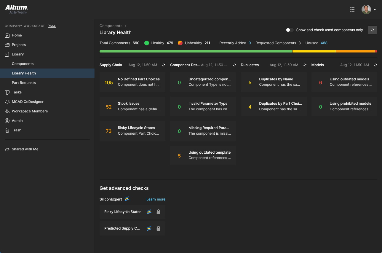
Both the Library Health summary on the Components view (above) and the Library Health dashboard information become populated once a component health check is run. This is performed automatically the first time the Components page is accessed, and also when refreshed ( ) in this dashboard view.
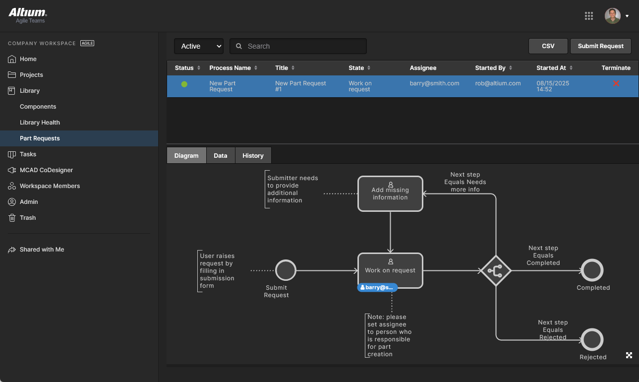
Part Requests
Related page: Creating & Managing Processes
This page enables you to create and manage requests for new components. An engineer can simply put in a request for one or more parts to be created and get notified when that request has either been completed, and the component(s) made available, or rejected (and why). The requestor supplies as much key information to support their request as possible (manufacturer and part number(s), description(s), any relevant datasheet (PDF or URL)). Stub Component Items also can be created that the librarian can then run with (and finish off).
Part Requests are defined by a Process Workflow and progressed to completion (Resolved) by the assigned user through the Tasks page – the details and command options are accessed from the Task Details pane. 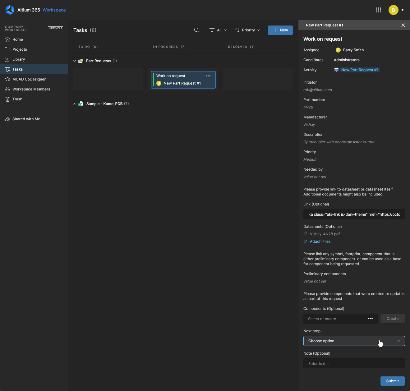 The Part Requests page lists Active or Closed request processes, with tab options that provides an active workflow view (Diagram), a table of all submitted request information (Data), and a sequential list of process workflow events (History).
Parts in Use
Related information: BOM Portal, Workspace Components
This page provides an aggregated overview of all manufacturer parts that are currently used in Workspace Projects and Managed BOMs. The listing is populated with key parameter columns (including SiliconExpert parameters if available) for each manufacturer part item, and includes active Used In links to the referenced BOM documents. The Parts in Use page allows you to quickly view all manufacturer part references that are applied in design BOMs while checking for active issues such as inappropriate Lifecycles, lack of standards compliance, or an extended manufacturing lead time. Note that the current report view can be saved as a CSV file using the download function ( ).
).

All Workspace Project and Managed BOM sources are included in the listing by default, as indicated by the view options menu above the list (All Parts). Select this menu to choose other available views, or the Create View option to select a new set of BOM data sources in the Select BOMs to Include in the View dialog window.
-
If a design project added to the View does not include an ActiveBOM document, then the Part Choices for its components will be listed in the created View.
-
Access to named Views that have been created in the Parts in Use feature is also available through the Projects page when the Parts Report filter option is selected. See Parts Report Filter for more information.
The listing's Used In column includes the associated BOM source name(s) where the part is currently used. This includes usage in Design Projects or Managed BOMs, or any of their Releases:
-
Where the part is used in a single BOM entity, hover over its name to view the related part designators. Click the entry to open the source in a new browser tab.
-
Where the part is used in multiple BOM entities, click the entry to view all the BOM sources with their related designators. Click on a source name to open it in a new browser tab.

Further insight into the current parts usage is provided by the Analytics summary information. This feature, opened from the listing’s  icon, populates the upper page area with notated group listings and graphic indicators representing key parametric measurement data for the current Parts in Use view. The analytics data will dynamically change as different custom views, with different BOM content configurations, are selected.
The Analytics data also interacts with the Parts in Use list by filtering its content. Navigate to and select a specific component Category (Component Type) or part Manufacturer to constrain the list to matching items, or click on a pie graph section, its label or a bar-graph item to filter the list to entries matching that parametric data – note that multiple filters can be applied (in an AND relationship). Deselect a parametric filter by clicking on it again, by closing its entry in the Filters area above the list, or by removing all applied filters with the Reset Filters option.
The Parts in Use interface offers a range of features for locating the information you need for assessing and auditing parts usage. These include column ordering, keyword searches and advanced column filters. When used in combination, the features offer a high degree of control over which entries are included in the Parts in Use report and how they are presented:
-
List order - Order the Parts in Use list entries by a specific set of parametric data by toggling the arrow option in that data column’s header. Click a header’s  icon to reorder the parts list in ascending order by that dataset, click again for the descending data order, and click once more to remove the list order defined by that column data.
-
Search – Limit the parts list entries to those that include keywords entered in the Search field, which is opened (and closed) with the  icon. The search is case-insensitive, includes all part parameter columns (except
 Used in), and highlights the found search terms in the listed results.

-
Column Filters – Constrain the parts list to entries that satisfy specific parameter data requirements set by column Filters. A Filter is configured in a column header’s  drop-down menu by checking one or more of the available parameter values, or for numeric parameters, by setting a From/To number range. Use the All option to toggle all checkboxes on/off, the Blank option (if available) to disable/enable entries where a value is not included, and the Search field to locate a specific value option. Note that multiple Filters can be enabled to tightly curate the report results.
Compared to filtering by Analytics element selection, column filters offer more flexible options such as removing specific list entries by disabling individual parameter values. 
Tasks
Related information: Working with Tasks, Web Viewer Commenting Window.
This page view allows you to access and manage all Tasks – job activity requests – that are currently active in the Altium 365 Workspace. Tasks are presented in a Kanban board flow style, with their progress state (ToDo, InProgress and Resolved) moving through Task rows. One row is reserved for general Tasks (those not associated with a project), and each remaining row applies to Tasks for a specific project. General Tasks are created from within the dashboard, and Project-specific Tasks are created by assigning a Workspace member to a project Comment.
Although presented through a relatively simple interface, the Workspace Tasks dashboard offers a flexible and efficient way of both managing and tracking workflows within the actual design environment rather than via an external system. This page is a global view of all Tasks that are currently active in the Workspace, while the project-specific Tasks view available from the navigation tree when viewing a project represents only those Tasks associated with that project.
MCAD CoDesigner
Related page: ECAD-MCAD CoDesign
This page relates to ECAD-MCAD CoDesign functionality. MCAD CoDesigner synchronizes the PCB design between electrical and mechanical engineers. It works directly with ECAD and MCAD data via the MCAD CoDesigner panel on the Altium Designer side, and a corresponding panel plugged into your MCAD software. The latter is provided through installation (and registration to the MCAD software) of the Altium CoDesigner plugin.
The following MCAD platforms are supported when using the latest Altium CoDesigner plugins:
The versions of MCAD tools officially supported will depend on the version of Altium CoDesigner plugin being used. This information can be found on the New in CoDesigner page.
 The MCAD CoDesigner page provides an overview of the area, along with links to the MCAD CoDesigner Plugins and further educational material.
The page offers the following:
Workspace Members
Related page: Managing Workspace Membership
This page is used to create and manage a list of Workspace users – people who are members of the Workspace and have access to the Workspace and/or its associated technologies.
User members can be those with Altium Accounts within your own organization, or those in a different organization (in the case of the latter, inviting them in as members of a Workspace does not mean they become part of your organization). You can also invite users who do not have an Altium Account (who will need to then register for one). Users can submit a request to join your workspace, and existing users can submit a request for another user to be invited to the Workspace.
 Determine which people are to have access to the Workspace from the Workspace Members page of the interface.
The tab options at the top of the page allow administrators to view all users with access to the Workspace, and manage any users requesting access to the Workspace:
-
Members – all users with member access to the Workspace based on their applied group membership and applied access permissions. The Members tab is the only view available to Workspace members not in the Administrator group. Administrators (only) can use an entry's options ( ) to Edit (managed Group assignments), Review Accesses (projects available to them), and Remove a user from the Workspace.
-
Guests – users who are external to the organization Workspace (non-members) that have been granted shared access to a Workspace project - see Sharing with External Users. Such users are indicated by an associated  icon.
icon.
-
Join Requests – request submissions by users of your organization who are seeking access to the company Workspace.
-
Invitation Requests – request submissions by members of the Workspace for allowing access to the Workspace by another user, or users.
Use the Search field to quickly find a member within the list.
Trash
This page presents all items that have been 'soft deleted' – items that have been deleted, but not yet permanently so. The Trash is essentially a recycle bin into which any item within your Workspace can be moved (through a soft delete action). It is isolated from the rest of the Workspace and so any item in the Trash is not available for use and cannot be found through searching, or through pages in the browser interface, or from within Altium Designer
You will know if a Delete-based command within the Workspace interface or Altium Designer is of the soft delete variety, as the subsequent confirmation window will confirm that the deleted item(s) will be moved to the Trash.
 When you delete an item in the Workspace through a soft delete action, it will be moved to the Trash. The Trash page provides the interface to this isolated area of the Workspace.
You will only see items that you yourself have soft deleted. An administrator will see all soft deleted items in the Trash. The listing includes column data corresponding to identification information, and when the item was deleted and by whom. You can sort by any of the columns – click on a column header once to sort in ascending order and click again for descending. Use the Search field above the listing to search across all content.
Select an item in the Trash, then use the controls at the top-right of the list to permanently delete that item, or to restore it, respectively. Corresponding commands are also available from the menu associated with the  control (at the far right of the selected item).
-
For a Project, only the owner or an administrator can (soft) delete or restore. For any other item, you will be able to perform these actions as long as you have editing rights.
-
Complete 'hard' deletion of an item (Permanently Delete) is possible for Workspace Administrators only.
.") Select an item, then decide whether to fully restore it for use again, or to permanently delete it (a 'hard delete' if you will).
Select an item, then decide whether to fully restore it for use again, or to permanently delete it (a 'hard delete' if you will).
Alternatively, to empty the entire Trash in a single, batch action, click the  button at the top left of the page. A confirmation window will appear alerting you to the fact that this action will delete all items permanently and that they cannot be restored thereafter. To proceed, click the
  button.
When attempting to permanently delete (hard delete) an item, you will be prevented from doing so if that item is used by a parent item – for example a component that is used on a managed schematic sheet, or within a design.
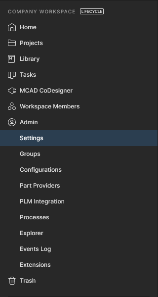
Admin-Only Interface Elements
The following sections summarize the elements of the Workspace browser interface that can only be accessed by Administrative users of the Workspace – those who are part of the Administrators group. Access to these elements is through the dedicated Admin area of the left-hand navigation tree.
Admin – Settings
This page provides a collection of sub-pages for the configuration of options relating to various features and services provided by, and through, a Workspace.
When changing any settings, be sure to click the  button, at the top-right of a page.
The left-hand side of the page provides a navigation tree with which to quickly access various sub-pages of settings. The following pages are available:
General
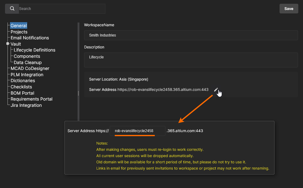
Use this page to change the name, server address and description for the Workspace as required. The page also provides read-only information about the Workspace's location. Changes can only be made by the Administrator who is also the Owner of the Workspace, and not by any other Administrator of that Workspace.
Projectѕ
Use this page to specify the default path (within the Workspace folder structure), and optionally the share permissions, for newly created projects. Projects will be created in the specified Default path for new projects folder entry unless a folder is already open (where it will be created), or a different path has been specified in the Create Project window’s Parent Folder field under the Advanced section – see Creating a New Project for more information.
Users who create or upload projects will require access to this default folder (initially Projects), which is determined by its sharing permissions as specified in the Workspace Explorer page – see Sharing Folders and Items for more information. Note that if a user does not have access to the default project folder (and other folder is not open), the system will create a Personal Folder structure that incorporates a My Projects folder for project storage – see Project Creation Without Folder Write Access for more information.
Permissions for a new project always include administrators and the user who created the project (its ‘owner’). Also included is the permission set inherited from its parent folder, unless this is overridden by the Default permissions for new projects option. When available and enabled, this option’s settings will impose a specified set of access permissions on newly created projects rather than those inherited from its parent folder – see Default Project Creation Permissions for related information.
 An administrator can define the default settings for newly created projects. Initially, the path is set to Projects and the Default permissions option is disabled.
Email Notifications
This page provides a control to enable the Workspace's email notifications feature. This facility flags a variety of events to key stakeholders, relating to component Items, projects and part requests.
See the Email Notifications page for more information.
Altium 365 uses the Amazon SES (Simple Email Service) as the sending email server. This is the same service that is used by Altium to send emails regarding an Altium Account (e.g. account activation).
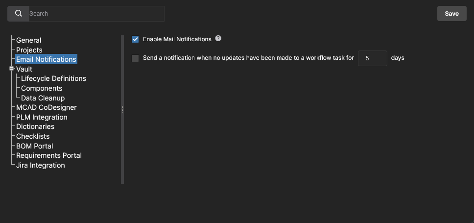
Also available is an advanced Process Workflows and an associated Send a notification when no updates have been made to a workflow task for <number> days notification. When enabled, users with an active Task that requires them to complete a workflow step will receive a reminder notification if no action has been taken for the specified number of days.
Access Control
The Access Control section heading groups together settings that are used to control the flow of Workspace data for security purposes. This option is available to administrators with the Altium 365 GovCloud or when the Altium 365 Organizational Security Package is enabled for your organization.
-
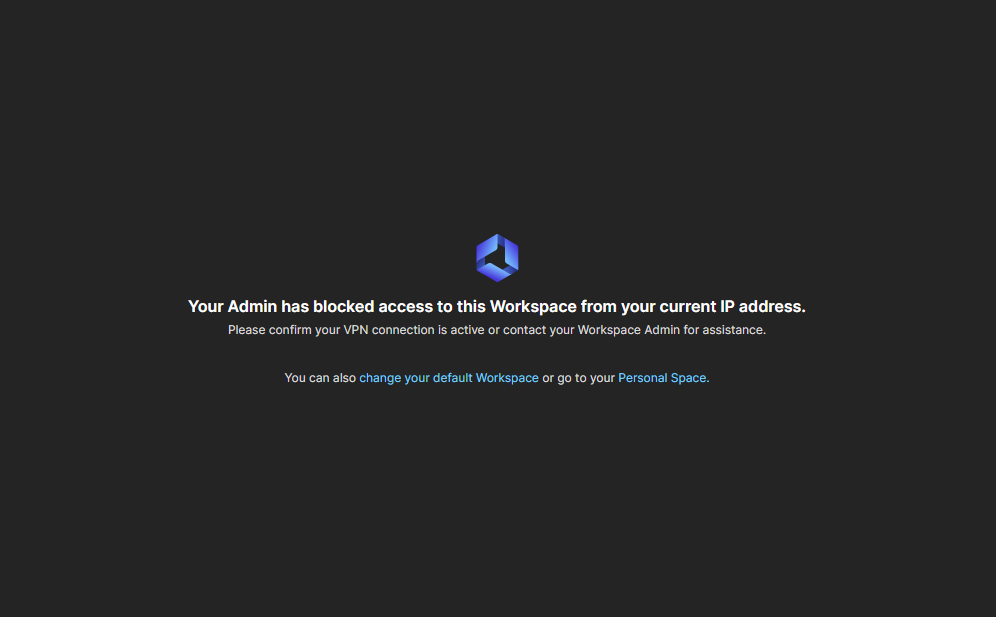
Inbound Traffic – use this page to specify the IP addresses, IP ranges or subnets that can access your Workspace. IP filtering is applied using the single-entry Classless Inter-Domain Routing (CIDR) notation method to block incoming connections outside of the specified IP range. Inbound Traffic Filtering provides finer control over who can connect to your company Workspace, and for example, might restrict incoming access to a range of accepted IP locations or the IP address of an official VPN configuration. Multiple IP filter entries can be added.
Users attempting a Workspace connection with an IP address that does not pass an applied filter receive a blocked access message.
-
Outbound Traffic – available in the US-based Altium 365 GovCloud Workspace only. Use this page to enable/disable specific traffic to external users or locations that are potentially outside the US, in line with company policies and government regulations. Each option presented in the page applies to data that may be sent from the Workspace when using that feature – see the associated notes for related information.
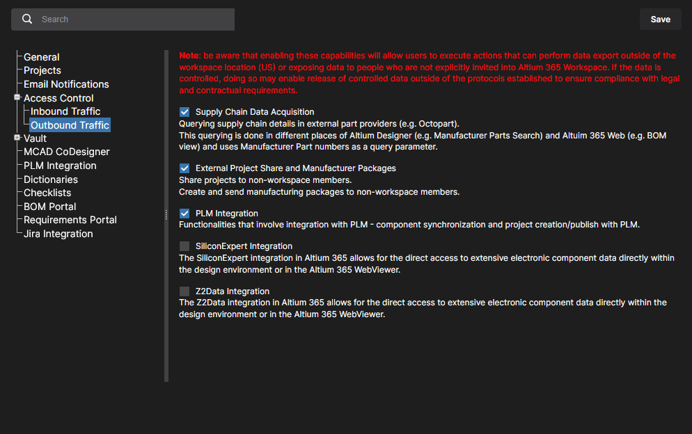
-
Supply Chain Data Acquisition: When unchecked, this option will disable data queries, such as Manufacturer Part Number (MPN) data requests, sent to external parts data sources. This will disable automated part queries sent to external parts data sources and services.
-
External Project Share and Manufacturer Packages: When unchecked, this option will prevent the sharing of design data with external users – those who are not registered members of the Workspace. Attempts to do so will be ignored or result in an error message.
-
PLM Integration: When unchecked, this option will prevent data requests sent to external PLM systems. During actions such as the synchronization of parts, Workspace component data will not propagate to the remote PLM instance, resulting in a LibSync error.
-
Silicon Expert Integration: When unchecked, this option will prevent component data requests being sent to the Silicon Expert manufacturer parts data service. An attempt to activate the service will result in a warning/error message. 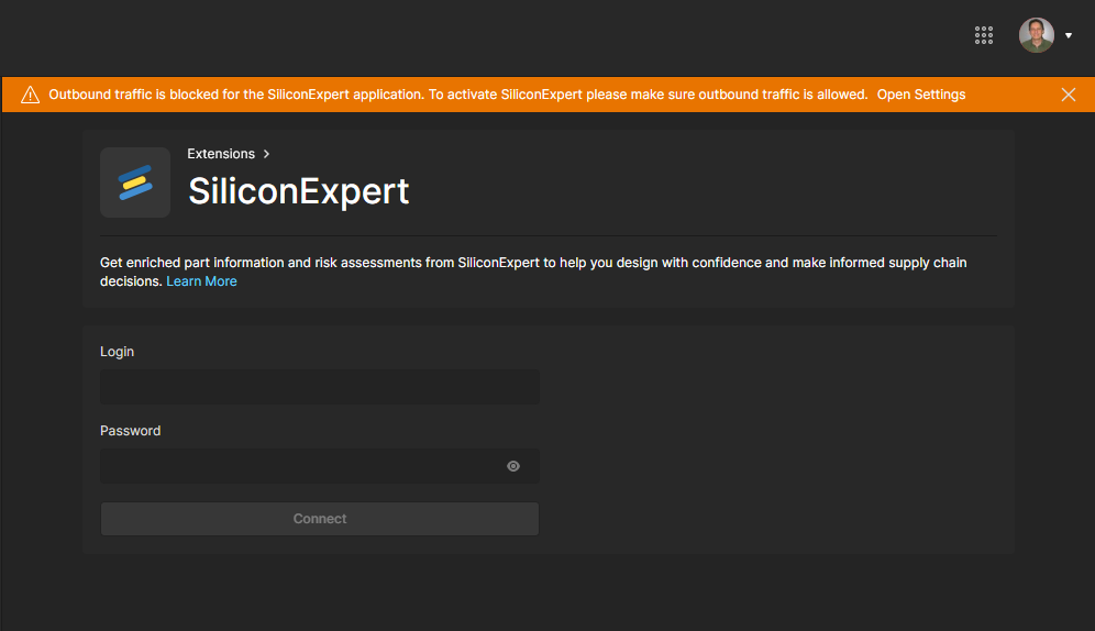
-
Z2Data Integration: When unchecked, this option will prevent component data requests being sent to the Z2Data manufacturer parts data service. An attempt to activate the service will result in a warning/error message. 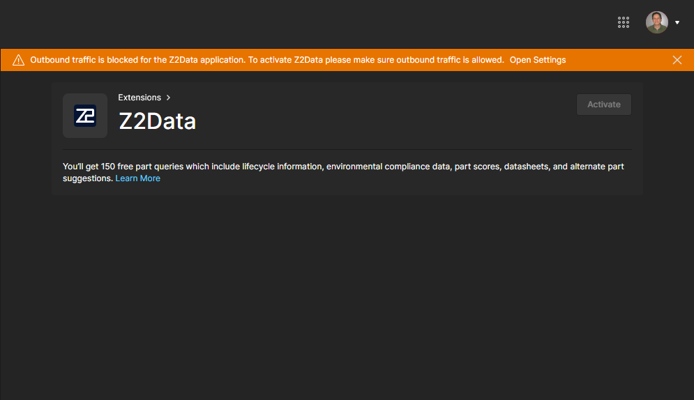
Vault
The Vault section heading groups together settings related to specific functionality within the Workspace itself.
-
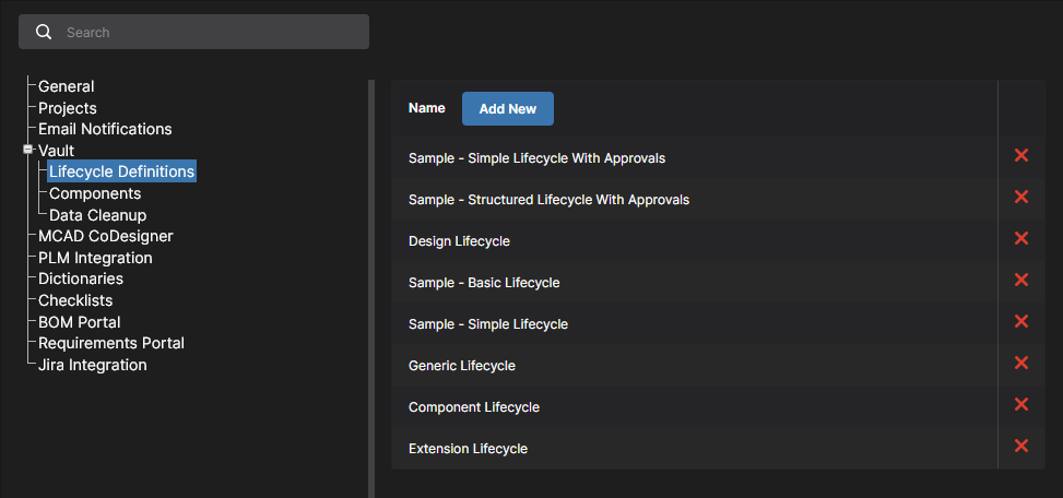
Lifecycle Definitions – use this page to define and manage your Workspace's lifecycle definitions, complementing the ability to do this through Altium Designer. Providing better visibility of the states and transitions involved, each lifecycle is built in a graphical way to show the flows involved.
This page also includes options for enabling additional features that will become available when editing Workspace-based components in Altium Designer (click to confirm a changed setting):
-
Data Cleanup – use this page to quickly delete data items from your Workspace. This is particularly useful after having experimented with creating and releasing content into your Workspace, for example when trying out the migration of unmanaged libraries, and now you want to 'flush' such experimental data. This functionality works on any and all Item types in your Workspace.
Use the available checkboxes to determine whether to delete all data items (All) or specific item types. With your cleanup strategy configured, click the  button. A window will appear asking for confirmation, and alerting you to the fact that this action cannot be undone. To verify and proceed, enter the text Delete my data permanently into the field and then click
  .
.
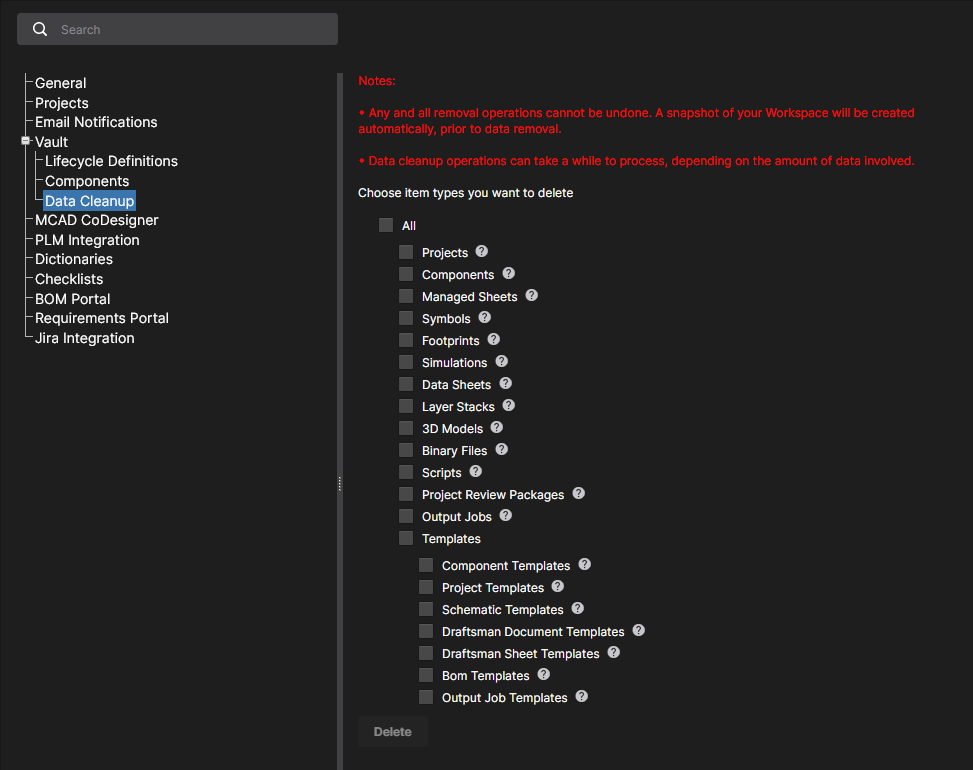
Note that child items cannot be deleted if already referenced (in use) by parent items. The parent items must be deleted first. For example if a component is being used on a managed sheet or within a design project, the managed sheet and/or project would need to be deleted first.
Remember that data cleanup is an action that cannot be undone. A snapshot of your Workspace will be created automatically prior to data removal. Note also that data cleanup operations can take a while to process, depending on the amount of data involved.
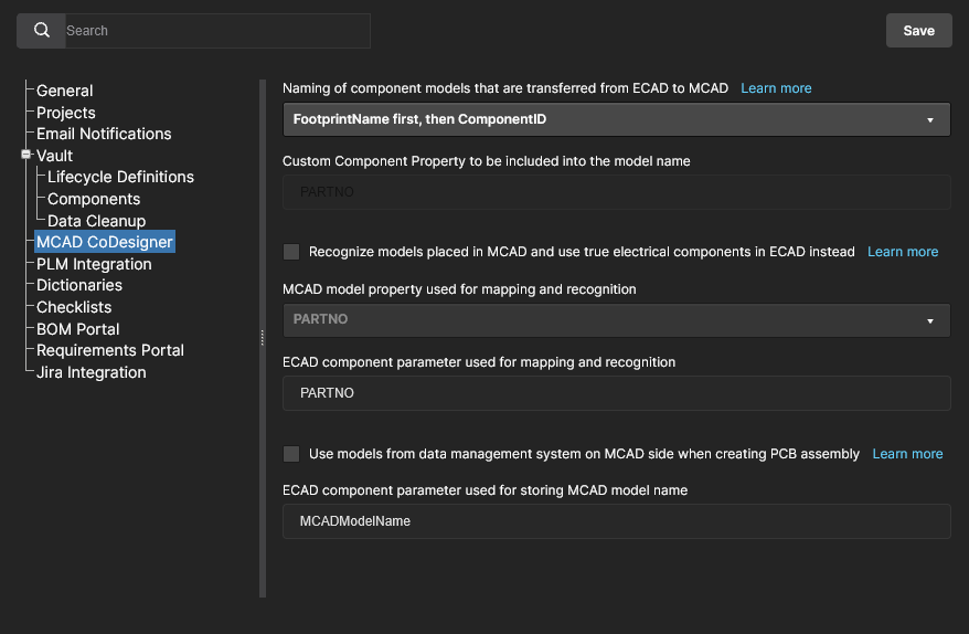
MCАD CoDesigner
This page provides controls to enable component recognition between the ECAD and MCAD domains, when using the ECAD-MCAD CoDesign feature. This facilitates the use of native components when a design is pushed and pulled between the two domains. The following options are available.
-
Specify how transferred ECAD models are named – set the naming convention used for models during the initial transfer to the MCAD domain. This is set to <FootprintName><ComponentID> by default, and can be changed to <ComponentID><FootprintName> or <CustomComponentProperty><FootprintName>. In the latter case, use the Custom Component Property field (otherwise set to PARTNO) to define the custom property you wish use in the MCAD component name. This option allows engineers to include meaningful information, such as detailed part number data, into the component identification.
-
Recognize models placed in MCAD and use true electrical components in ECAD instead – enable this option to support use of native components when the board is being Pushed from MCAD and Pulled in to ECAD. The MCAD 3D model is linked to the equivalent Altium Designer component, so when the board is pulled into Altium Designer the MCAD 3D model can be replaced by an instance of the fully-defined Altium Designer component footprint, complete with a 3D model. Use the two sub-fields to determine the MCAD model property and the ECAD component parameter, used to identify components in the two design domains. By default, these fields are populated with the entry PARTNO. The MCAD model property can be your own custom property, or choose MCAD model name from the drop-down. The ECAD component parameter can also be your own custom parameter. These fields are required if the parent option is enabled. If one or both are left blank, the button will be disabled.
-
Use models from data management system on MCAD side when creating PCB assembly – enable this option to support the use of native components when the board is being Pushed from ECAD and Pulled in to MCAD. The MCAD software gets the model of the component from the MCAD's data management system (by the model’s name) and then places that component on the MCAD PCB assembly, instead of the model that came from ECAD. Use the sub-field to determine the ECAD component parameter that will be used to store the MCAD model name. By default, this field is populated with the entry MCADModelName. This field is required if the parent option is enabled. If left blank, the button will be disabled.
MCAD-to-ECAD component linking is available for all supported MCAD platforms (except Autodesk Fusion®). ECAD-to-MCAD native component linking is currently only supported in:
SOLIDWORKS – requires SOLIDWORKS be connected to a SOLIDWORKS PDM system. The MCAD component must be defined in the ECAD component as a parameter, in the form "<vault>:folder\folder\component.sldprt", where <vault> is the name of the PDM vault. Consult your SOLIDWORKS documentation for information on how to connect to a SOLIDWORKS PDM system. If the component is not available in the SOLIDWORKS PDM system, CoDesigner places the model transferred from the PCB editor and saved in the Altium 365 Workspace instead.
PTC Creo Parametric – requires PTC Creo to be connected to a PTC Windchill® server, with the ECAD components stored in a Windchill Workspace. Consult your Creo documentation for information on how to connect to Windchill. If the component is not available in the Windchill Workspace, CoDesigner places the model transferred from the PCB editor and saved in the Altium 365 Workspace instead.
Siemens NX – requires Siements NX to be connected to Siemens Teamcenter PLM. Consult your Siemens NX documentation for information on how to connect to Teamcenter PLM. The MCAD component reference must be defined in the ECAD component as a parameter that includes the Teamcenter path, with the parameter value in the form :root_TC_folder:subfolder1:subfolder12:model_name.
CoDesigner checks these settings on startup (from Altium Designer and from the MCAD tools). Restart your design software if the settings have been changed in your Workspace.
PLM Integration
Available when PLM Integration is enabled for your Altium 365 Workspace. This page provides an Enable new PLM Configuration option, which when unchecked, reverts the PLM Integration user interface back to the previous system based on uploading edited configuration files.
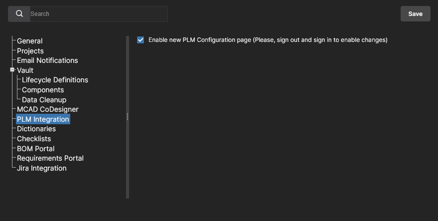
See PLM Integration for information.
Dictionaries
Use this page to create custom parameters with several defined values (Dictionaries) that can be applied to Component Templates through Altium Designer. Multiple parameter Dictionaries can be added, with each entry containing a listed choice of corresponding parameter values. When used, this approach provides a more formalized control over the application of parameter data, where standardized parameters and their value choices are centrally managed in one accessible location.
 Create predefined lists of parameter values using the Dictionary option under Admin - Settings.
To add a Dictionary entry, click the  button and then enter an appropriate parameter type name in the following Create Dictionary window. Add parameter values using the
  option associated with the Dictionary entry's name – press
 Enter to confirm the entered value.
 Multiple Dictionaries can be created with multiple parameter values.
-
Double-click on an entry or use the associated  option to edit a Dictionary name or value.
-
Use the associated option to add a new value to the Dictionary.
-
Use the associated  option to delete a value entry or the Dictionary entry itself.
In Altium Designer, Dictionaries created in the Altium 365 Workspace become available as Parameter data Types when creating or editing a Component Template. Where that Template is used for creating a new component – or when editing a component based on that Template – the Dictionary-defined parameter entries will offer only those value choices defined in the Workspace Dictionary. Note that Dictionary-based parameters are indicated by their associated icon.
For more information, see Support for Dictionary-defined Component Parameter Data Types in Altium Designer's Component Editor.
Checklists
This page includes the listing of the available compliance Checklists that apply to project Design Reviews. Each named Checklist is composed of multiple, descriptive-based items that can be confirmed as ‘checked’ during the Design Review process. The list includes two sample Checklists (PCB and Schematic check) that can be used as supplied, or as a basis for custom Checklists.
Existing Checklists can be edited or deleted, and additional Checklists created from the  button. A list’s collection of check items is composed of simple text statements on multiple lines – press Enter to add a new line.
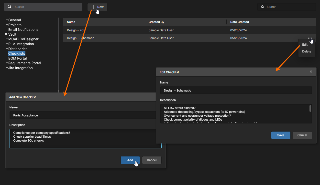
New Checklists also can be created, edited and saved from the Overview page of a Design Review instance.
See Design Reviews for more information on working with Checklists in Design Review instances.
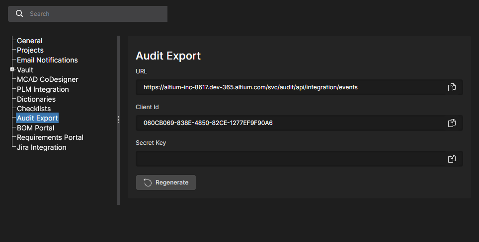
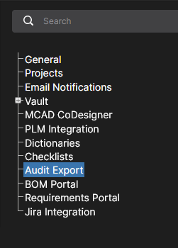
Audit Export
This page provides the configuration settings for exposing the Altium 365 Workspace Events Log data to a suitable SIEM (Security Information and Event Management) system for compliance and auditing purposes. The Workspace API allows your organization’s security specialist to configure your SIEM system to retrieve audit data from Altium 365 using the Client ID and Secret Key parameters specified in this page by a Workspace administrator.
Note that the Altium 365 SIEM API is available when the Altium Organizational Security Package has been purchased and enabled for your Workspace. See Organizational Security Package for more information.
Open the collapsible section below to see related technical setup information for security specialists.
Audit Logs Exposure Usage
The Altium 365 API information provided here is intended for an organization’s security specialist, who should use the support available from their SIEM solution when setting up data importation from Altium 365.
This web service is designed for auditing and tracking events within a Workspace. The API supports Limit Pagination, and authentication via a Client ID and a dynamically generated Secret Key. In the request response, detailed information about events can be found in the JSON format, while fields are named according to the Common Event Format (CEF).
Please note that this service is available only with a valid license. Access and utilization are restricted to licensed Workspaces.
How to use the Service
-
How to get endpoint and parameters
To access the service endpoint and parameters, users with administrative rights should navigate to the Admin – Settings page in the Workspace.
If the Workspace has the necessary license, the Audit Export option will be available.
Selecting this option will display a page with the URL for data retrieval, along with the Client Id and Secret Key. If it is the first time accessing this page, the Secret Key field will not be populated. To obtain it, click the  button. If the key has already been generated it will be available immediately.

If there is a need to invalidate the current key for any reason, the  button action will be available after generation. This action prevents data retrieval using the previous, now revoked, key.
Use the  button associated with each field to copy its contents when required.
-
How to use Endpoint
Overview
This API endpoint is designed for retrieving audit events. To retrieve data, we employ limit pagination. This means we return the total number of events and the current set of events determined by the Limit and Offset parameters. For example, on the initial request for event data, a user may not provide any parameters at all – in this case, we return a set of events with default parameters.
Alternatively, a user can specify parameters in their request, such as Offset = 0 and Limit = 500. In this case, we will return the events starting from the very first one up to the specified limit. If there are fewer events than the specified limit, then all available events will be returned.
It is important to note that users of this API should maintain their current position in the logs on their side in order to sequentially request events. For instance, if there are 1000 events and a user initially passes Offset = 0 and Limit = 500, then the next request should have Offset = 500 to retrieve the remaining events.
Authentication
Access to this endpoint requires the provision of a client identifier (ClientId) and a client secret (ClientSecret) in the request headers. If one of them is missing or incorrect, an Unauthorized response is returned.
Request Parameters
Offset (optional): The offset from the start of the result. Allows control over which record to start returning data from.
Limit (optional): The maximum number of records to return. There is a limit on the maximum allowable amount, which must not exceed the set maximum for this API.
Responses
200 OK: The successful response contains audit events that meet the specified criteria.
400 Bad Request: Returned if the number of records specified in the request exceeds the maximum allowed limit.
401 Unauthorized: Returned if client authentication failed due to missing or incorrect ClientId or ClientSecret headers or missing the license.
Example of request
 GET your-endpoint-url?Offset=0&Limit=500
 Headers:
     ClientId: your-client-id
     ClientSecret: your-client-secret
Response
Standard response for API requests that return audit events in the JSON format with fields named according to Common Event Format (CEF).
Object Definition
Standard response Object Structure:
TotalCount (int): The total number of records available for retrieval. This value represents the count of all events that match the request criteria.
Events (List of Events): A list of events formatted in the JSON CEF format. Each item in this list represents an individual event.
Event Structure:
CefVersion (string): The version of the CEF format. (Current version = 1)
DeviceVendor (string): The identifier for the device manufacturer. In combination with DeviceProduct and DeviceVersion, it uniquely determines the type of the sending device. (Predefined: Altium)
DeviceProduct (string): The product identifier of the device. In combination with DeviceVendor and DeviceVersion, it uniquely determines the type of the sending device. (Predefined: 365 Platform)
DeviceVersion (string): The version identifier of the device. In combination with DeviceProduct and DeviceVendor, it uniquely determines the type of the sending device. (Predefined: Cloud)
DeviceEventClassID (string): A unique identifier for each event type.
Name (string): A human-readable title or description of the event.
Extension (Object): An object containing details of the event.
Extension Structure:
Dvchost (string): The fully qualified domain name (FQDN) of the device, when available.
Msg (string): A message further describing the event.
Rt (DateTime): The time the event was received.
Dtz (TimeSpan): The time zone of the device that generated the event.
Suser (string): The name of the source user associated with the event.
Act (string): The action mentioned in the event.
ExternalId (string): The ID used by the originating device. These values are typically sequential and associated with each event.
Cat (string): The category assigned by the originating device. Devices often use their own categorization schemes to classify events.
Response Example
{
    "TotalCount": 2,
    "Events": [
        {
            "CefVersion": "1",
            "DeviceVendor": "Altium",
            "DeviceProduct": "365 Platform",
            "DeviceVersion": "Cloud",
            "DeviceEventClassId": "",
            "Name": "User Login",
            "Extension": {
                "dvchost": "host.domain.com",
                "msg": "User successful login",
                "rt": "2024-01-10T14:30:00Z",
                "dtz": "UTC+00:00",
                "suser": "sampleuser",
                "act": "login",
                "externalId": "45678",
                "cat": "authentication"
            }
        },
        {
            // Additional Events
        }
    ]
}
BOM Portal
The Altium 365 BOM Portal application allows you to create data-rich BOM procurement documents from Workspace design projects or uploaded (CSV/XLS) ECAD BOM files. Using Altium’s comprehensive data services, the Portal’s Managed BOM documents include up-to-date component manufacturer information and live Supply Chain data from multiple sources. The web-based system is automated, highly configurable, and offers advanced search capabilities for determining the optimal component parts for your design projects.
See the BOM Portal page for more information.
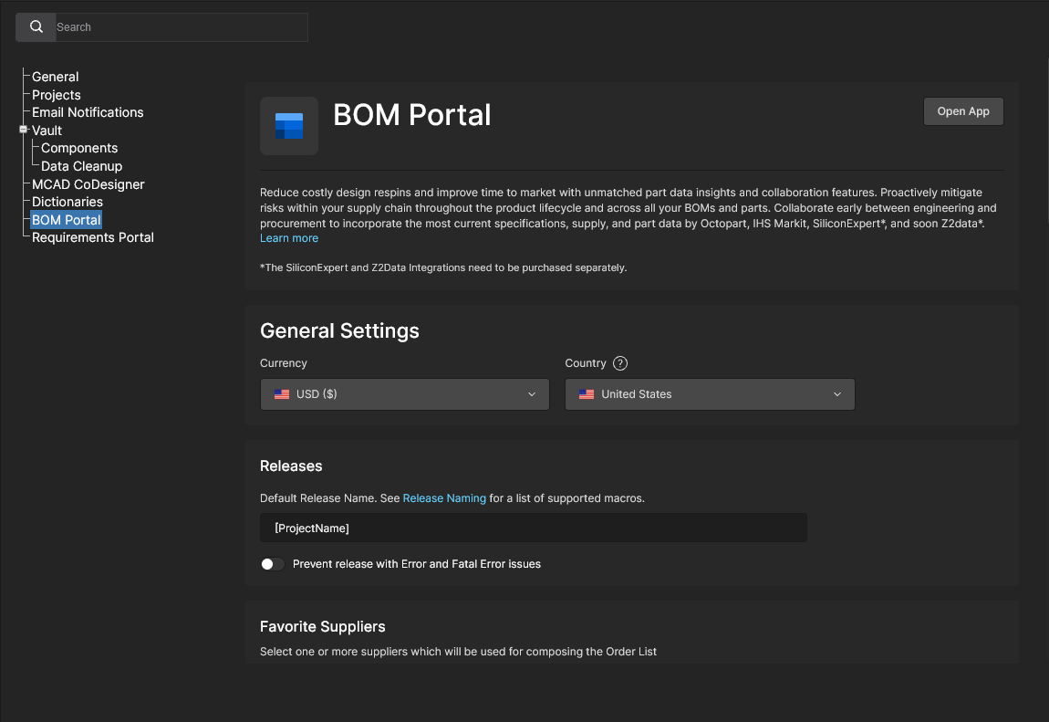
Use this setup page to specify the default settings for newly created/uploaded Managed BOM documents. The settings can be changed from these defaults in individual Managed BOM documents through the BOM Settings window.
-
General Settings: Specify the default purchasing Currency and Country settings. These are independent, so the preferred purchasing currency is not bound to location.
-
Releases
-
Favorite Suppliers: Specify the default parts vendors that are enabled for Managed BOM documents. See the BOM Portal’s Order List section for more information. Note that the available suppliers included in the Favorite Suppliers list are in turn defined by the Altium Parts Provider settings in the Workspace Part Providers page.
-
Checks Manager: Specify how BOM line Issues are reported in BOM documents. Each type of BOM validity check can be changed to report at any of the available Report Levels, including the option to ignore a check (No Report). See the BOM Portal’s BOM Checks section for more information.
Scroll to view the full BOM Portal configuration options.
Requirements Portal
Requirements Portal is an advanced system engineering application that integrates with Altium 365 to define and manage technical requirements for project designs. Requirements instances created in the portal can be placed in Altium 365 Workspace design documents and also assigned as user Tasks. Compliance with a Requirement definition can then be verified within the project design space, the status of which is synchronously reflected in the Requirement instance in Requirements Portal.
See Working With Requirements for more information.
The synchronous link between your Altium 365 Workspace and Requirements Portal is defined by mapping a Workspace project to a portal’s System Design Block that has associated Requirement definitions. The link can be established in different locations:
-
In the Requirements Portal web interface by assigning an Electronics type Block to a Workspace design project – related information.
-
In a Workspace design Edit Project window by assigning a portal Block to a Workspace design project – related information.
-
In Requirements Portal entry view in the Workspace Admin - Settings page (as shown here) by adding a new Project-Block link to the Link Requirements list – see below.
Use the Requirements Portal option from the nine-dots menu ( ) to open the Requirements Portal interface in a new browser tab.
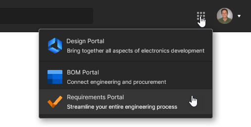
Jira Integration
Altium 365 Jira Integration enables bidirectional data synchronization between Atlassian Jira® issues and Altium 365 Workspace Tasks. The integration allows the remote creation of Jira issues directly from your Altium Workspace as dedicated Jira Tasks, or existing Jira Issues can be linked to a Workspace project.
Once a Jira Issue to Workspace Task relationship is established, its Comments and status settings (priority, progress, assignee) are synchronized in real time, which provides enhanced and interactive project management insight into Altium design projects in the Jira space. Jira integration is configured by mapping Workspace projects to a specified Jira Project.
See Working With Jira Tasks for more information.
The Jira Integration setup page includes the following additional options:
-
The  button opens the default view for your Jira account in a new browser tab.
-
The  button will disconnect the Jira application from your Jira account, as listed under Jira Connection. This reverts the Jira Integration page to its initial pre-setup configuration.
-
When the Enable Jira mapping for project editors option (under Access Settings) is enabled, members of the Workspace can map a project – provided they have editing rights – to the Jira project specified by this configuration. The project mapping is performed from the project Edit window – view a mapping access example. Workspace administrators can map design Projects to Jira Projects via the project Edit window regardless of this access setting.
Admin – Groups
Related page: Managing Workspace Membership – Groups
This page is used to create and manage a list of user (Workspace member) groups. Groups allow you to further organize your Workspace members according to, for example, the particular section of the organization in which they are involved, or the design team they are in. Groups also make the sharing of Workspace content, and the configuration of other served technologies, more streamlined.
Use a Group entry's options to manage its user membership (Edit), view projects shared with the Group name (Review Accesses), and delete the Group category (Remove).
 Access and manage the groups defined for your Workspace from the Admin – Groups page of the interface.
Several sample groups are defined for a Workspace, including the group Administrators. This group gives administrative privileges to its members. Anyone who is a member of this group has complete access to the Workspace and all associated technologies and services through its browser interface.
Admin – Configurations
Related page: Environment Configuration Management
The Configurations page provides the means to formalize the working environment for Workspace members based on their assigned Group. In practice, configuration instances are used to constrain each designer's Altium Designer working environment to use only company-ratified design elements, including templates, output job configuration files, workspace preferences and more. Any number of Configurations may be created and assigned to user Groups (Roles) as required.
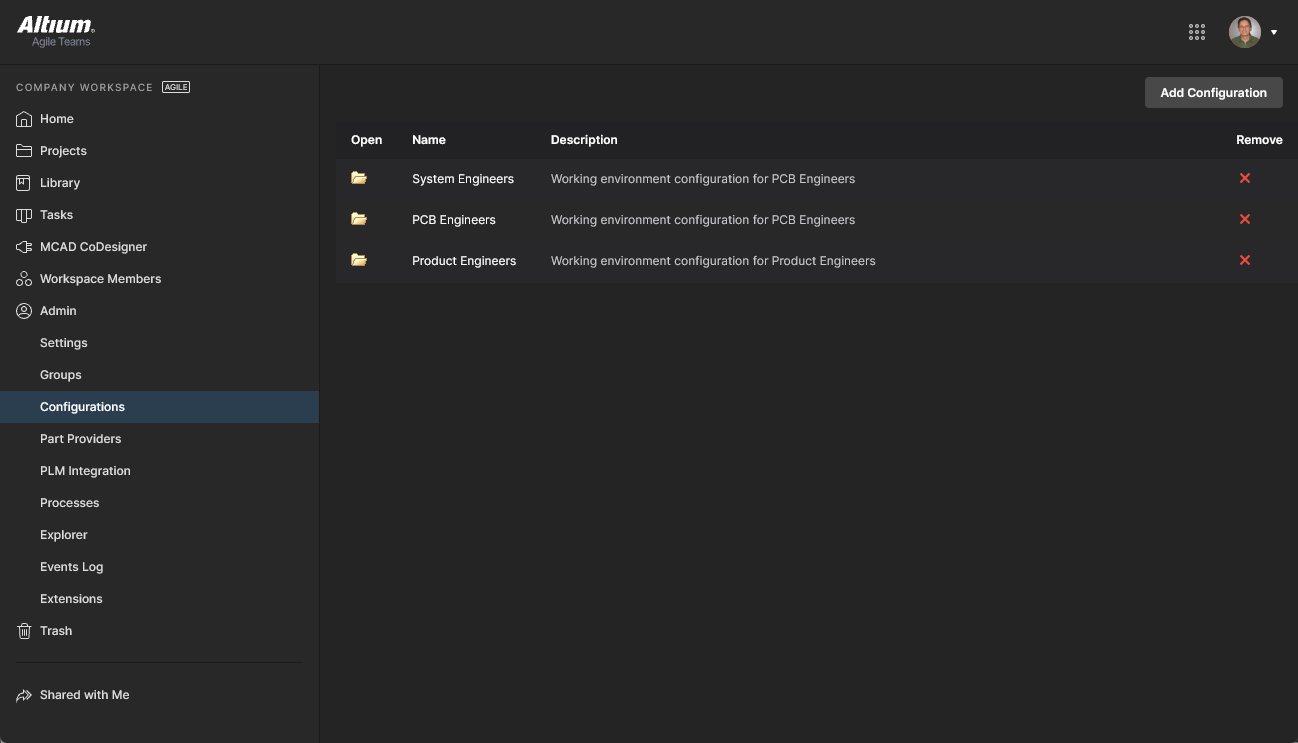 Define and manage designer environment configurations through the Workspace Configurations page.
Admin – Part Providers
Related page: Part Source Configuration
This page enables you to define a Part Source – facilitating centralized supply chain management, with designers across the entire organization using the same approved list of Suppliers, with which to source supply chain intelligence for parts used in their designs.
The following part sources are available for a Workspace:
-
Altium Parts Provider – an aggregate supplier data service that provides access to live component information from a comprehensive range of parts suppliers.
The Altium Parts Provider settings that are established in a Workspace will override those in Altium Designer when a user connects to that Workspace.
-
Custom Parts Provider – for situations where component supplier data is (and must be) sourced from an internal company enterprise system that provides a proprietary set of parts supplier data, which might be based on a tightly approved range of vendors and/or special pricing structures. This part source is actually configured for synchronization through Altium Designer – using a Custom Parts Provider Synchronization Configuration document (*.PrtSync) – allowing the supplier data from a specified database source to be mapped to Workspace supply chain data.
The actual supply chain intelligence – comprising Manufacturer (and part number), Supplier (and part number), Description, Pricing and Availability – is sourced from the Workspace's local Part Catalog and the relevant Part Source.
Each Workspace instance has its own dedicated Part Catalog. This is a part catalog database, dedicated to the management and tracking of manufacturer parts and their associated supplier parts. The catalog is installed as a service (Part Catalog Service), provided through the Altium 365 platform, and works only with the Workspace.
The Part Catalog stores items representative of actual Manufacturer Parts, along with one or more items representative of Supplier Parts – the incarnations of those Manufacturer Parts, as sold by the Suppliers/Vendors. Each Supplier Part is a reference to an item in a parts database – either the aggregate parts database of the Altium Parts Provider (which itself interfaces to, and gathers the parts from, enabled Suppliers), or a linked local parts database.
 Enabling required Suppliers and determining Location/Currency ranges for the Altium Parts Provider.
Admin – PLM Integration
Related page: PLM Integration
This page provides the interface to the Altium 365 Workspace PLM Integration service. It is from here that you define the interconnection with a PLM instance and enable/configure synchronization of your PLM components with those in the Workspace.
The Workspace facilitates the uni- or bi-directional synchronization of component data with your company enterprise systems. Interaction between the Workspace data and the enterprise system – typically a PLM system – is configured and managed through the PLM Integration page. This provides an automated interface for easily configuring the interconnection, mapping parameter data, and specifying the direction of data synchronization. Component data synchronization between the Workspace and target enterprise system uses a built-in synchronization process which may be manually triggered or set as a timed repeating event.
The Workspace provides support for the following PLM systems:
 PLM integration setup is performed through an automated interface for easily configuring the interconnection, mapping parameter data, and specifying the direction of data synchronization.
Admin – Processes
Related pages: Creating & Managing Processes, Defining a Process Workflow
This page provides the interface to create and manage Process Workflows that formally guide a company's designers through typical, everyday design processes such as:
-
Requesting new library parts.
-
Performing project-related activities, such as review activities or publishing to a PLM.
-
Creation of new projects.
Each Workflow that is used to implement a particular design process is created as part of a Process Definition. It can therefore be referred to as that process's underlying Workflow, or simply a Process Workflow. Processes and their Workflows are created and managed through the Processes page interface, where a range of predefined processes can be enabled for use or cloned and modified to suit your needs using the included Process Workflow Editor.
Admin – Explorer
Related page: Managing Content Structure & Access
This page gives you access to the structure of the Workspace, and is similar in presentation and layout to that of Altium Designer's Explorer panel. From here, you are be able to browse the folders and Items within the Workspace. You also can create and edit folders, and so build the structure of the Workspace, without having to be connected to that server through Altium Designer.
Folder-level and Item-level sharing also can be defined from this interface – controlling who is able to see what content in the Workspace and, at the folder level, whether other users can simply view a folder and its content, or also edit it (effectively releasing/committing/uploading design data into it). Content can be downloaded from the Workspace, directly from this interface.
Note that many of the Explorer page functions, particularly in terms of managing folders and projects, can be performed through the Workspace Projects page and Library features.
 Browse and define the structure of your Workspace as well as defining access to, and being able to download, its content.
You can soft-delete folders and Items from the Admin – Explorer page – sending them to the isolated Trash area for the Workspace.
Admin – Usage and Billing
This page provides information on subscription and user allocation for the Altium Develop solution.
On the Usage and Billing tab of the page, you can manage your Altium Develop subscription. In the Simultaneous Authors region of the page, you can also see the lists of users who are currently connected to the Workspace from Altium Designer Develop. A user can be disconnected by clicking the  icon, thus freeing the author seat for another user.
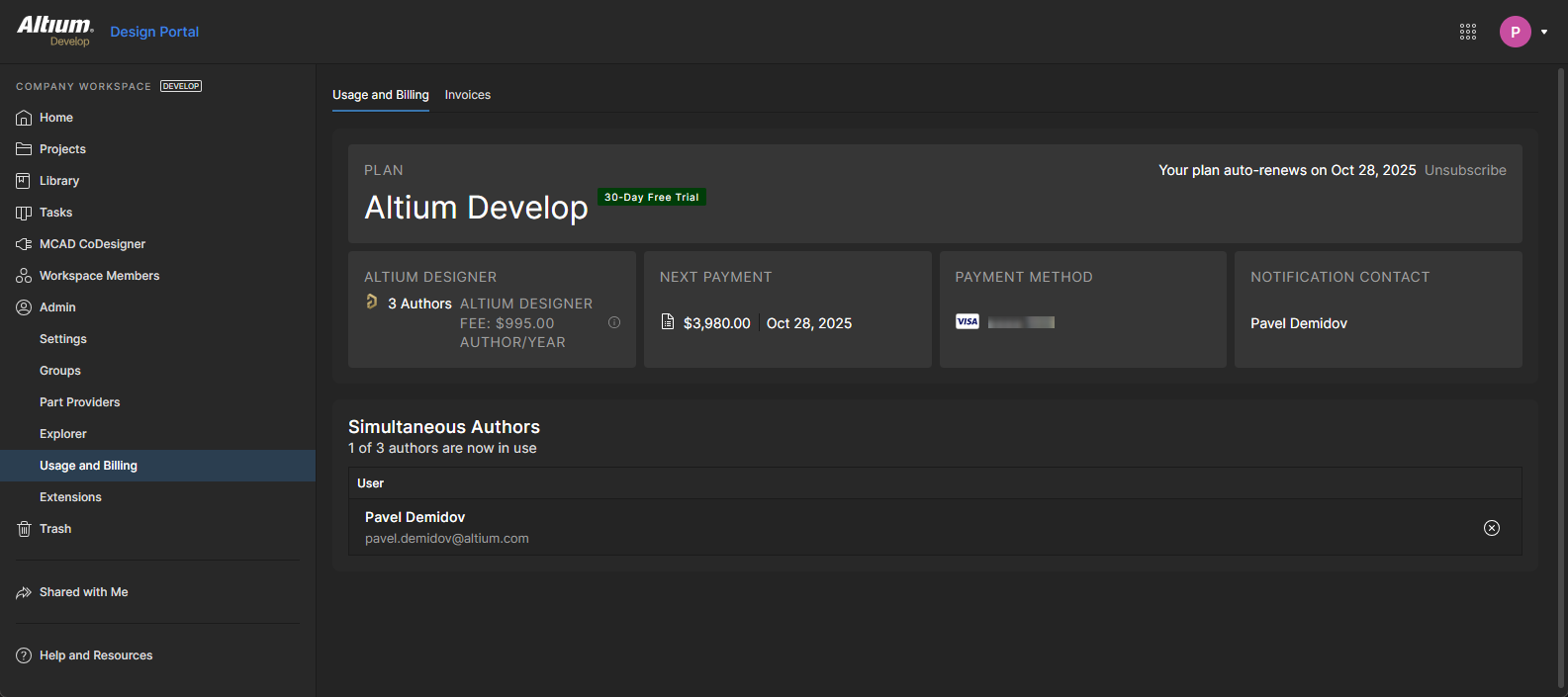
The Invoices tab of the page includes the history of your financial actions for the Altium Develop subscription.
Admin – Events Log
The Events Log is a sequential list of notable Data and User events that have occurred in the Workspace. It provides a single point of access for administrators to monitor and audit key Workspace activity for data governance purposes. This option is available to administrators when the Altium 365 Organizational Security Package is enabled for your organization.
The logged events include the addition, removal and group assignment of Users (Workspace members), the addition and removal of design/component data, and the sharing of that data with users. Detailed information is included for each event entry such as when it occurred, who invoked the event, and what object or User was affected.
 The administrator's Events Log records significant events related to design data and user access.
Use the view's Search field to filter the events list to those of interest, based on the entered search term.
Refresh your browser's view (F5) if recent events have not yet appeared in the log.
Events Log Export to SIEM Systems:
The Altium 365 Workspace provides an API for transferring Events Log data to a suitable SIEM (Security Information and Event Management) system for compliance and auditing purposes. Note that the Altium 365 SIEM API is available when the Altium Organizational Security Package has been purchased and enabled for your Workspace. See the Audit Export entry above for more information.
Admin – Extensions
This page provides setup access to additional licensed services available in your Workspace. Workspace Extensions are presented as selectable tiles, which provide access to additional information and configuration options for that service.
Click on an Extension tile to launch the service's setup view, where you can specify its connection credentials and any associated settings as required.
SiliconExpert
Altium 365 SiliconExpert Integration provides direct access to an additional set of advanced manufacturer parts data that is available to your BOM Portal documents, project BOM documents and the Library Health analysis. The enhanced parametric data sourced from SiliconExpert populates Workspace BOMs as specific parameter columns (YTEOL, Inventory risk, etc). SiliconExpert's advanced parametric parts data and ranked alternative part suggestions are also available when accessing Supply Chain Information features in Altium Designer.
This service is fully available for use when you have purchased an Altium SiliconExpert Integration license. To enable this service, open the SiliconExpert application by selecting its tile, enter the credentials provided to you by Altium, and then confirm the settings ( ). Also note that you can sample the benefits of integrating SiliconExpert with your Workspace by activating a trial period (
 ).
).
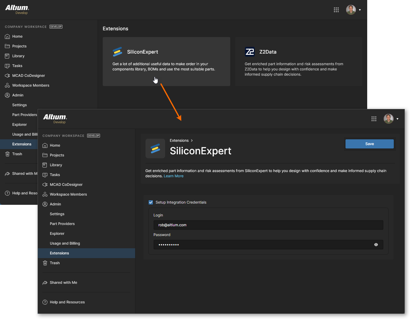
Once your SiliconExpert service connection is established, the SiliconExpert Integration view will be populated with information relating to your account. This includes a configurable list of reporting levels and parameter data:
-
Information in the Part Quota Details section includes your current SiliconExpert parts data quota limits and usage.
-
The Checks Manager section includes the default Report Level settings for SiliconExpert parameter values. Use the drop-down list associated with each entry to choose a different reporting level (Fatal/Error/Warning) or the No Report option to prevent a value condition from being reported. Note that you also can edit the Years to End of Life values (in years) that will trigger the three YTEOL report levels.
-
The Data Visibility Settings list includes all SiliconExpert parameters available to you. Use the parameter checkboxes to toggle their visibility in parts data listings (project BOMs, Managed BOMs, etc) for both Altium Designer and your Altium 365 Workspace – hover over  icons associated with parameters to see related information. Note that the base SiliconExpert
 YTEOL and Lifecycle parameters are always available, and their visibility state cannot be toggled.
Scroll to view the full SiliconExpert configuration options.
Z2Data
Altium 365 Z2Data Integration brings enhanced manufacturer part information and supply chain data directly into your Workspace. The rich proprietary data sources from Z2Data help you make more informed decisions about the selection and procurement of parts used in your designs. Z2Data integration in Altium 365 is implemented in a similar manner to SiliconExpert Integration as outlined above, and is available in BOM Portal documents, Alternate Parts, and Workspace Component Part Choices.
A Z2Data application tile is included in the Admin – Extensions page when Z2Data Integration is enabled for your Altium 365 Workspace. Select the tile to open the Z2Data application and then the  button to invoke basic access to Z2Data resources.
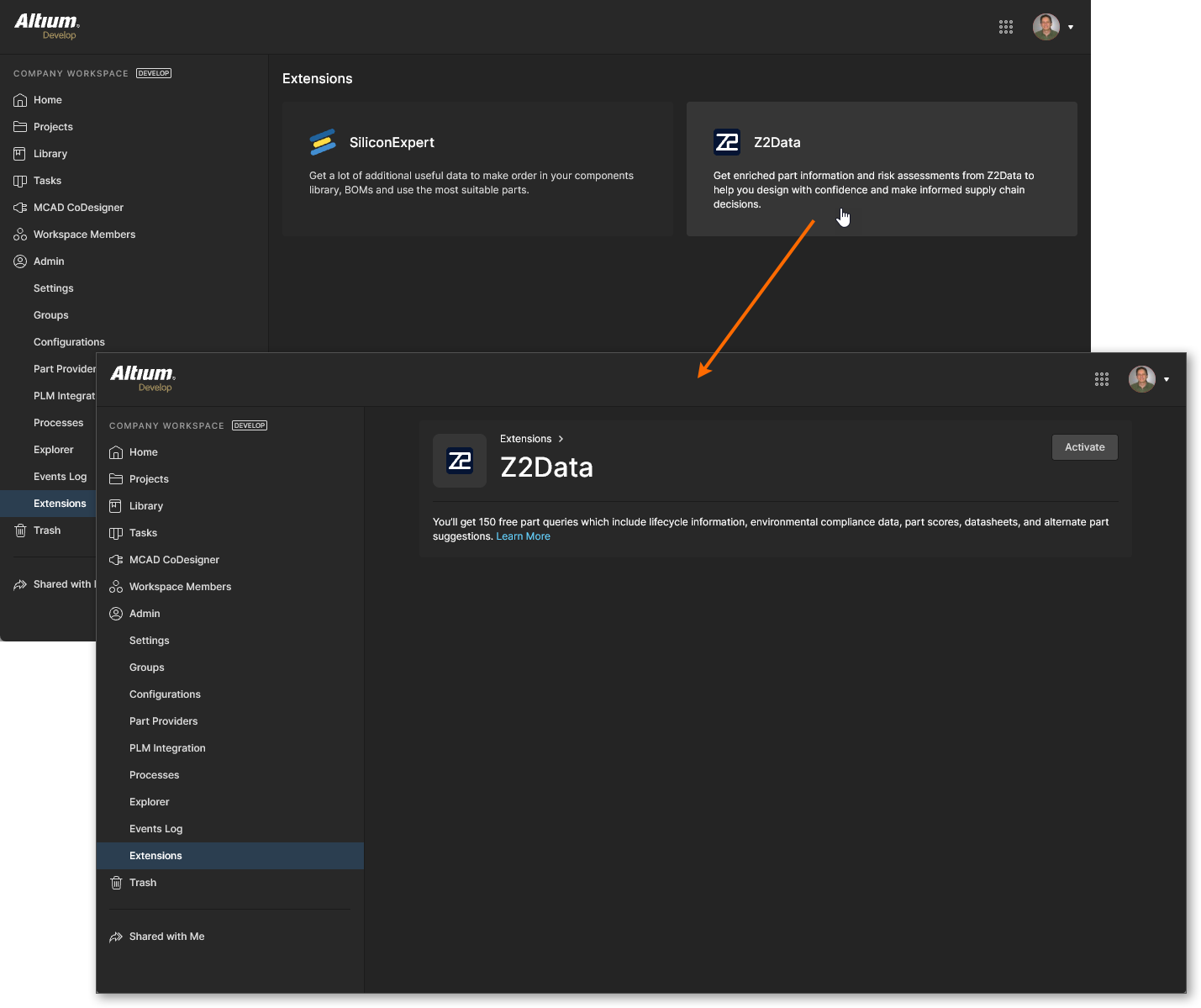
Once your Z2Data access is active, the Z2Data Integration view will be populated with information and settings relating to your current level of access:
-
Information in the Part Quota Details section includes your current Z2Data parts data quota limits and usage.
-
The Checks Manager section includes the default Report Level settings for Z2Data parameter values. Use the drop-down list associated with each entry to choose a different reporting level (Fatal/Error/Warning) or the No Report option to prevent a value condition from being reported. Note that you also can edit the Years to End of Life values (in years) that will trigger the three YTEOL report levels.

Note that you also can purchase an advanced level of access to Z2Data, which includes a large parts data quota plus a significantly expanded set of information and risk assessment details. Click the  button or go straight to the Z2Data access form.
