Empower Your Designs
with Advanced
Power Analysis
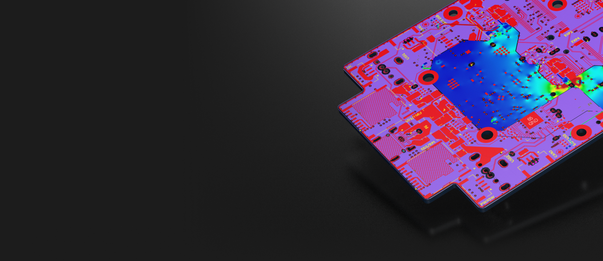
Avoid thermal issues and last-minute surprises. Power Analyzer delivers real-time insights into current flow and voltage drop - built right into your Altium design flow.
Simple and intuitive visualization tools
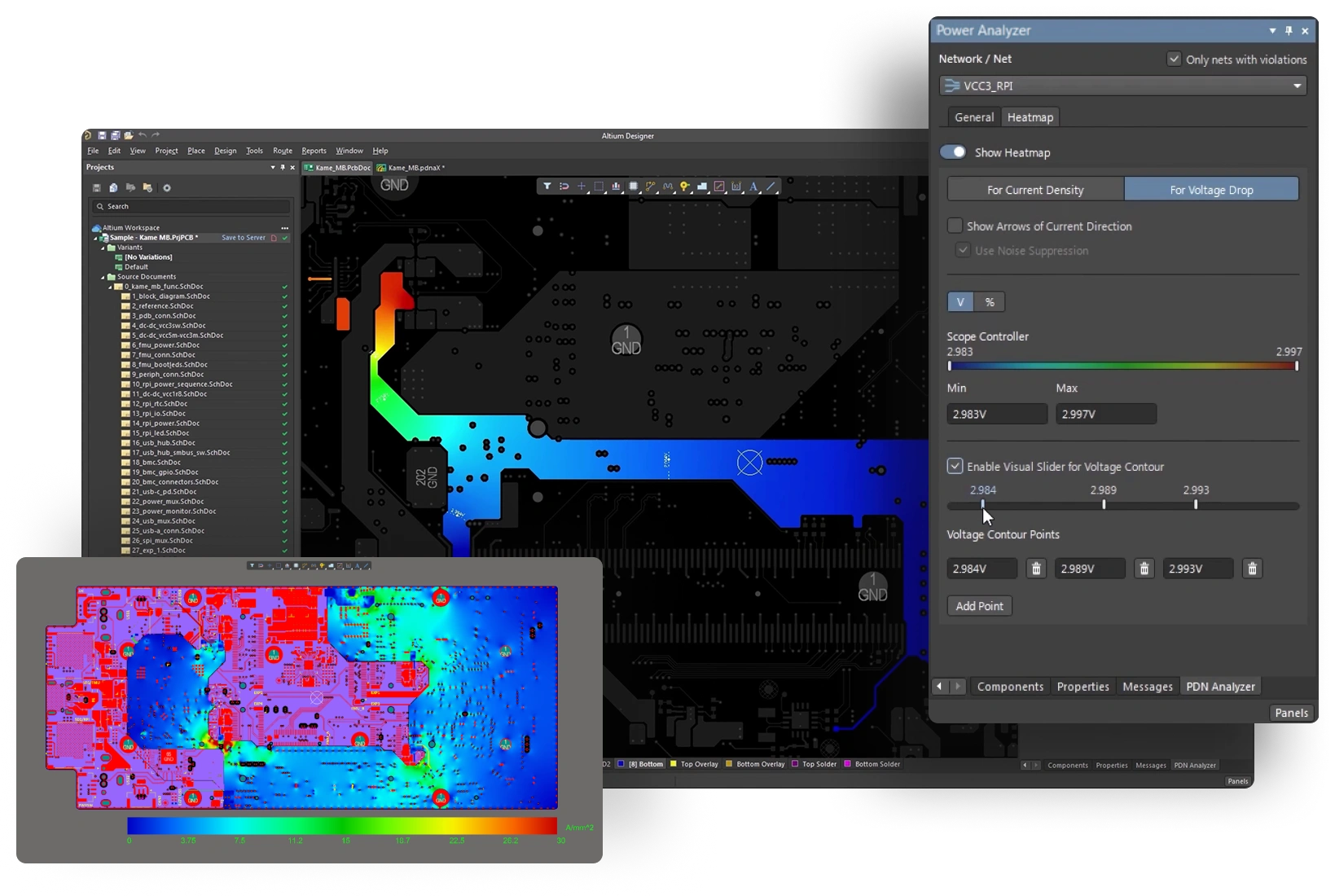
Power Analyzer gives you a simple, intuitive way to visualize voltage and current density distribution, current direction, and thermal hotspots. Results are displayed directly in the Altium Designer layout editor, letting you see how your power nets interact with the rest of your design.
No lab coat required
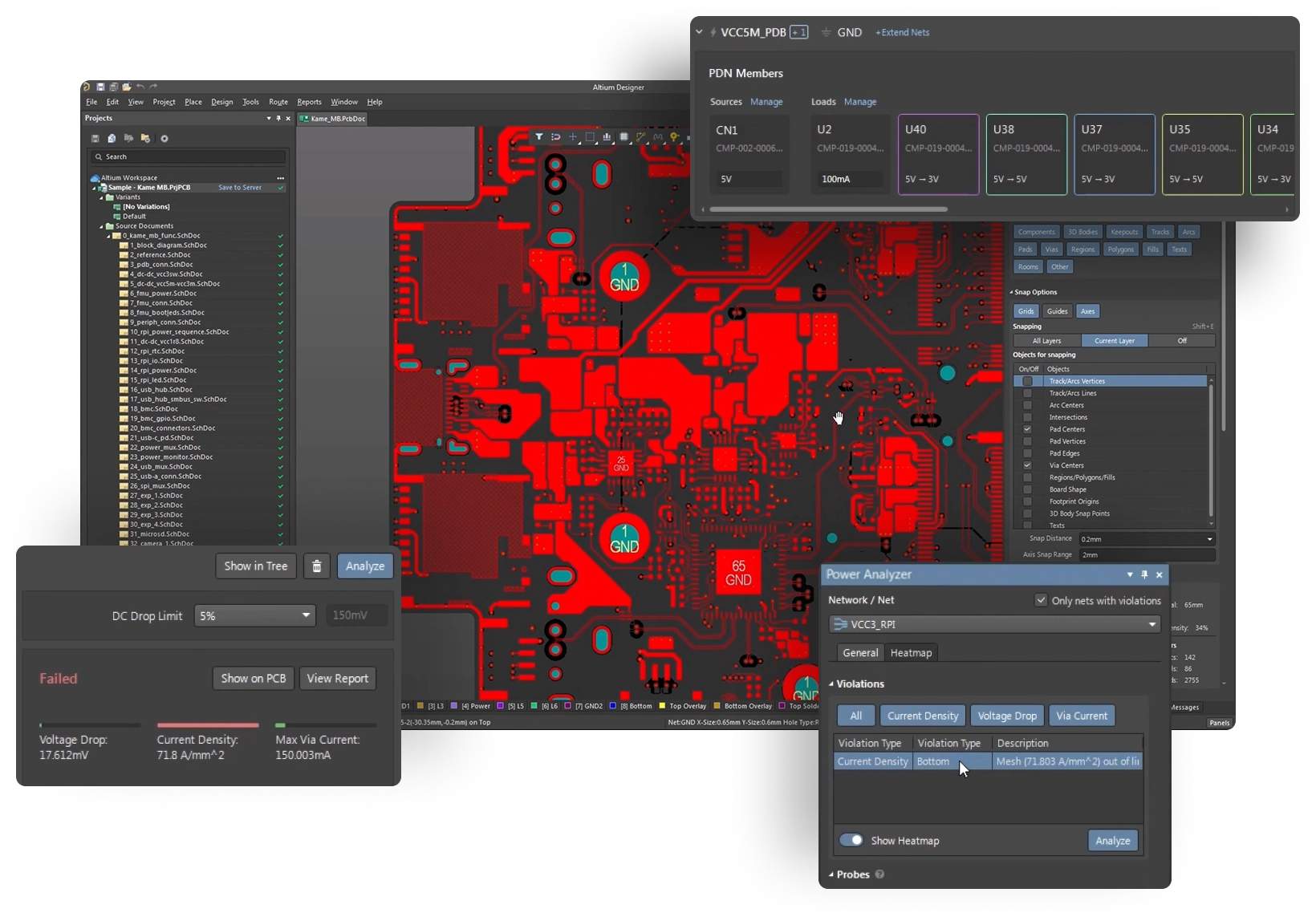
Quickly identify and resolve your DC voltage and current density issues during your board layout process without prior DC analysis experience.
Easily check your power system reliability
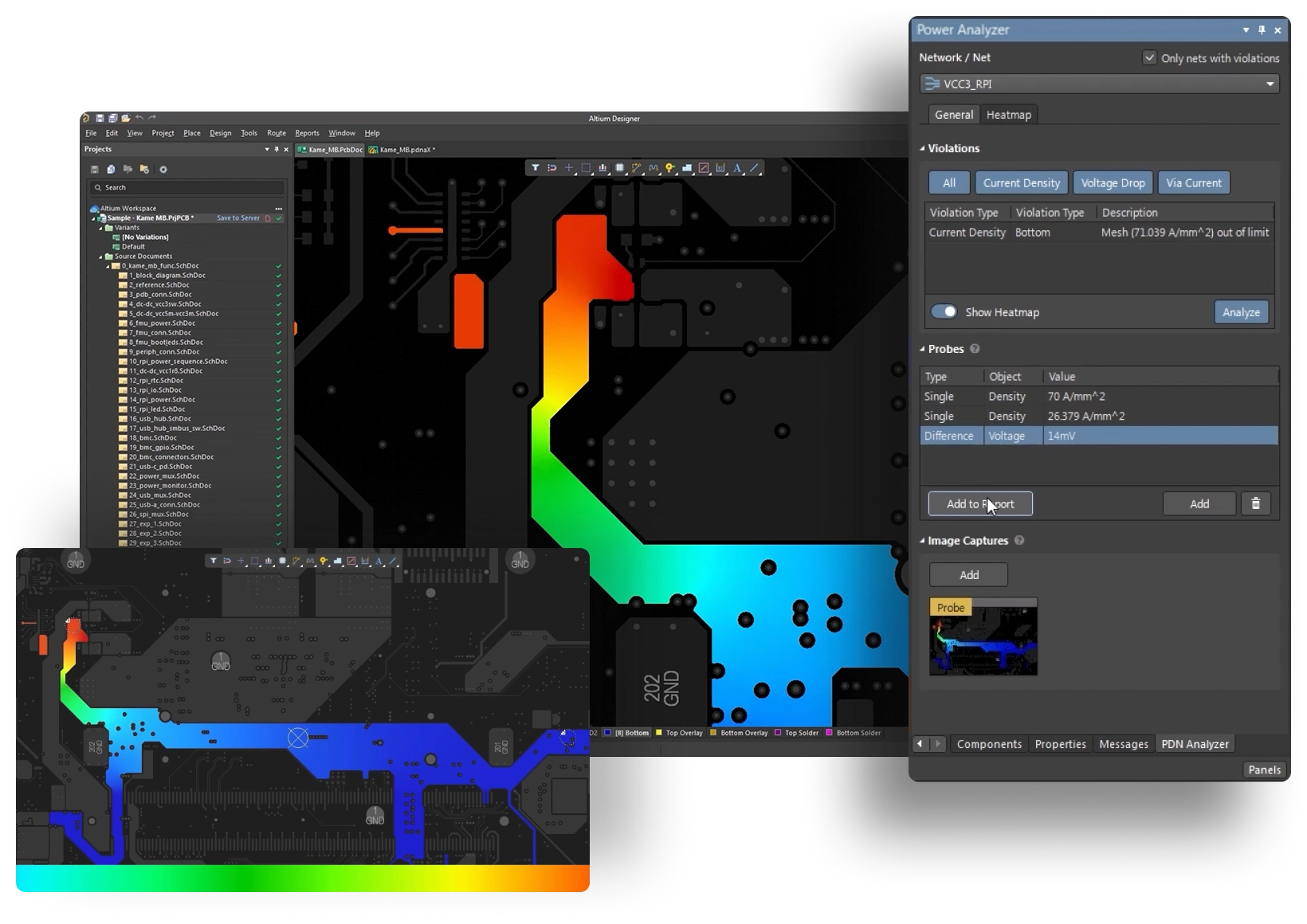
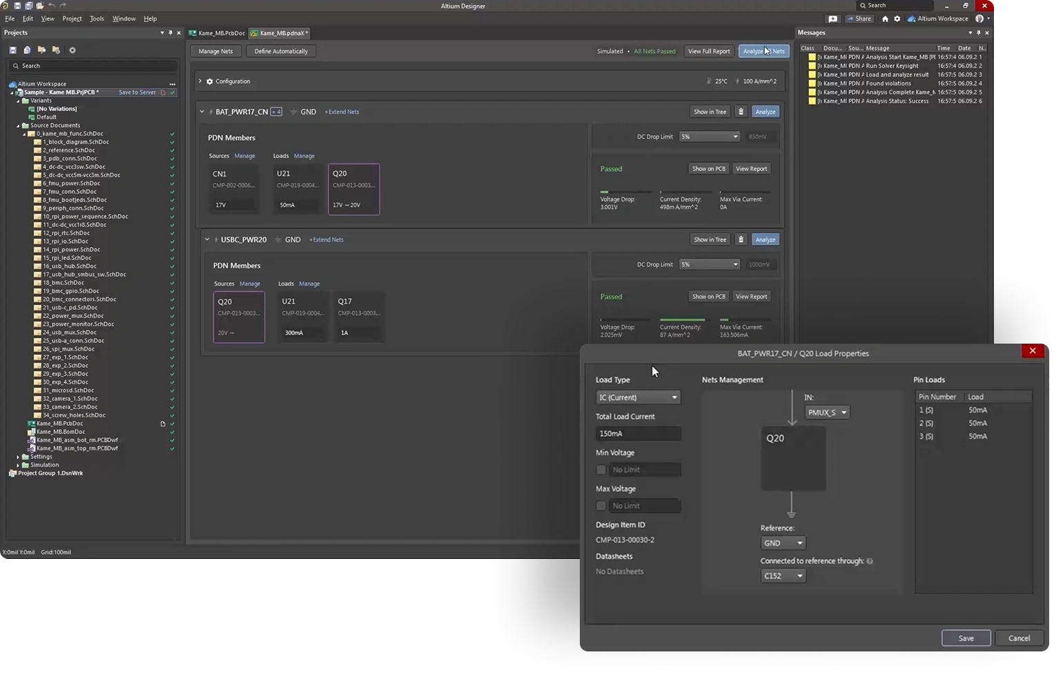
Design confidently, backed by accurate power measurements. Power Analyzer makes it easy to measure voltage, current density, or via current, either at a single point or differentially between two points, directly within Altium Designer. View results and make adjustments as you design.
One-stop design and review solution
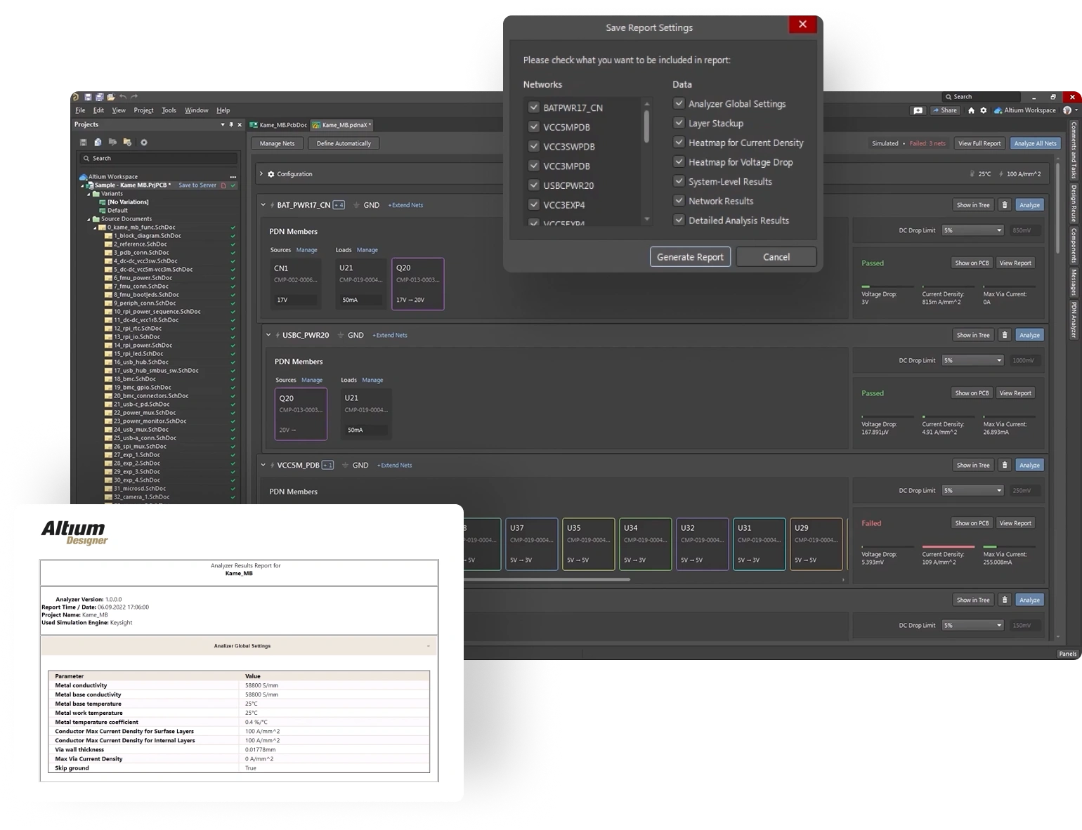
Configurable HTML reports make it easy to keep a record of your simulation work, including voltage and current margins, power consumption data, and custom screenshots. With sortable tables and an intuitive interface, you can get the information you need quickly and easily.
Simultaneous multinetwork simulations
Simulate multiple voltages simultaneously to gain a more accurate picture of your design. Our unique Voltage Regulator Models (VRMs) capture interactions between power networks while simplifying setup and reducing simulation time.


Start your free trial today!
Which version of Altium Designer do you use?
Get Access to Signal Analyzer
Connect with a Sales Representative to get started with Altium Designer
To trial or purchase this extension, you’ll need a current version of Altium Designer
Start Free Trial
To receive a free trial please follow these instructions
Current Altium Designer license is required for a trial license
1. Install Signal Analyzer extension first
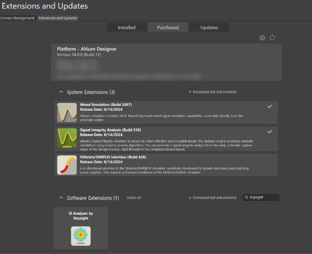
After installation Restart Altium Designer Panels
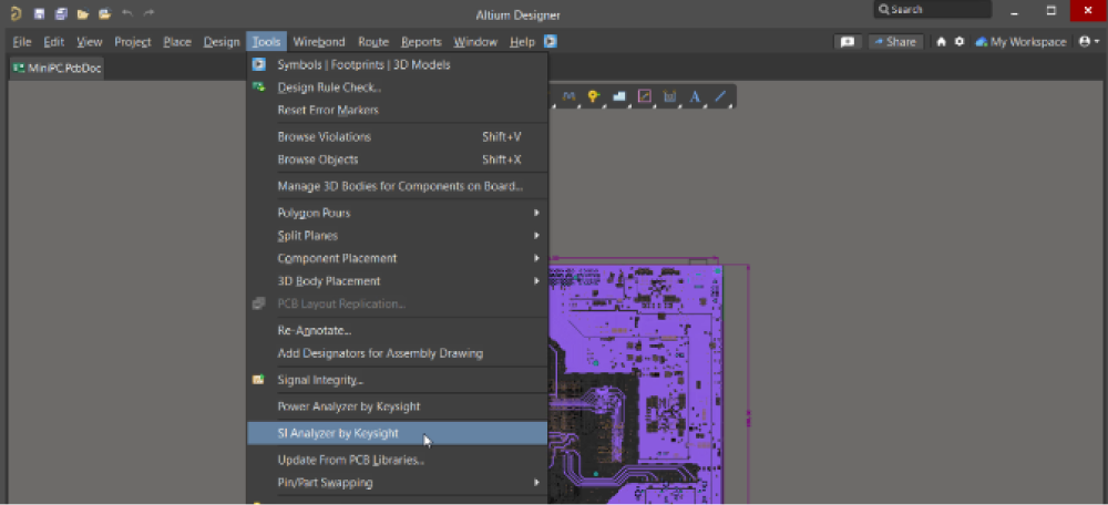
2. In PCB or schematic opened run Tools > SI Analyzer by Keysight
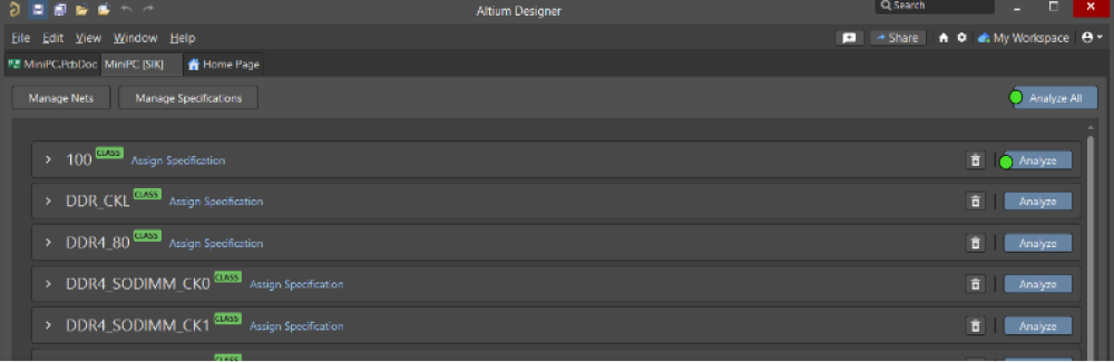
3. Click Analyze or Analyze All Nets
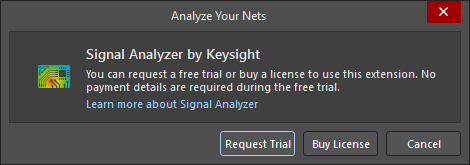
4. Request Trial or buy license in appeared window

You’re All Set
Get Access to Signal Analyzer
Fill out the form, and a sales representative will reach out to confirm your eligibility and help you get started
To trial or purchase this extension, you’ll need a current version of Altium Designer
Altium Designer represents 35 years of continuous innovation in PCB design. Developed for designers at every level, Altium Designer delivers the world’s first and only truly connected PCB design experience in one easy-to-use solution.
Make Smarter Design Decisions with Signal Analyzer
- Fully integrated in Altium Designer
- Real-time signal integrity analysis
- Intuitive visual feedback
- No expertise required
- Detailed & shareable reports
- Quick iteration & adjustment
“Working with designs including many high-speed interfaces I used to spend days making sure signal integrity is in order. I decided to give Signal Analyzer a try and it was much better than I expected - calculating impedance and propagation time without switching to external software is a real time-saver and I find it more precise than other tools.”
“Dealing with high-speed signals has never been easier – Signal Analyzer supports my daily design challenges, starting from PCB stackup adjustments, signal integrity and propagation analysis, and ending with PCB corrections such as copper fills or even vias placement. The design of PCIe buses or even single-ended signals related to high-speed multi-channel ADCs/DACs or 868 MHz / 2.4 GHz transmission lines can be optimized and aligned with project constraints, saving a lot of time.”
Frequently Asked Questions
No, Altium Designer 24.3 or higher is required to use the Keysight Signal Analyzer extension.
No, your board information is being analyzed locally.
Yes. You can analyze DDR single-ended and differential traces with signal analyzer. The result will be impedance, delay, insertion loss and return loss.
The highest frequency of the insertion loss and return loss is 20 GHz, which translates to roughly 10 Gbps. The impedance calculation and time delay should be reliable and higher than 10 Gbps.
Yes.
- Transmission lines are modeled as 2D cross-sections and solved by FEM.
- To speed up via analysis and to retain accuracy, lumped element models are created from the dimensions of each via.
The trace traversal algorithm in the engine uses 2D FEM to solve for the characteristics of the transmission lines.
Yes. Dk and Df values for impedance and loss.
Yes, Signal Analyzer considered the reflections from via stubs. The via stub resonance is also captured.
The accuracy of the impedance calculation is within ±0.1% of the result from the commercially available, industry-trusted impedance solver from Keysight ADS.
Altium Power Analyzer
by Keysight Technologies
Get Started with Power Analyzer